Route breakdown during the installation of overhead power lines
 Overhead line breakdown call a set of works to determine on the ground the design directions of the line and the places to install supports.
The route must be laid on the ground so that after the construction of the line, the following are ensured: normal conditions for the movement of vehicles and pedestrians, convenience in maintenance and repair of all elements of the line.
Distances from overhead line supports and conductors to various underground utilities and overhead structures are given below.
Name of the site near the route of the overhead line The smallest distances, m Underground pipelines, sewer pipes and cables 1 Fire hydrants, water columns, wells (hatches) of underground sewage 2 Gas dispensers 5
The routing of the overhead line begins with the fact that with the help of the theodolite, the direction of the first straight section of the line is determined, and then two landmarks are installed in this direction: one at the beginning of the section, and the other at a distance of 200 - 300 m from it (depending on visibility conditions).
According to the received direction, in the places of the supports specified in the project, poles are temporarily installed, which are removed from the ends of the line section to check their correct location in the alignment of the constructed overhead line, and then these poles are removed by are replaced by signs.
Each picket sign shows its number, as well as the design number of the support that will be installed at that location. Picket marks are placed in the center of the future foundation pits.
Pits for single-column supports and A-supports installed along the line should be located along the axis of the line with their long part, and pits for A-supports installed across the alignment of the line should be perpendicular to the axis of the airline route.
At the point of changing the direction of the line on the corner support in the form of A, it is necessary to pre-break the angle of rotation of the route. To do this, taking the support for the top of the corner (see the figure), place equal segments AB and AC in the direction of both sides of the corner. Then points B and C are connected, and the midpoint of segment BC is connected to point A.
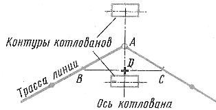
Breaking the pit under the corner anchor (A-shaped) support
Line AD will be the angle bisector.The pits for the overhead line supports will be located on this bisector and must be spaced from point A at the same distances determined by the solution of the legs of the support being installed.
It is recommended to break pits for A-shaped supports using special templates, the use of which allows you to quickly and most accurately perform this operation.
Line rotation angles are indicated by corner marks. The sign of the corner picket shows its number, the value of the angle of rotation of the line and the project number of the support.
The ground route breakdown is checked against the project. Existing deviations from the project are eliminated or agreed with the design organization and then proceed to digging foundation pits.