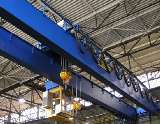
Installation of electrical equipment on overhead cranes
 The following electrical equipment is installed on electric overhead cranes: electric motors, starting and regulating resistors, brake electromagnets, controllers, protective, ballast, signaling, blocking and lighting devices, limit switches, current collectors, etc., made depending on the conditions of the environment, in which the faucet operates, in steel pipes, ducts, open, etc.
The order of crane installation work is as follows: first, all steel boxes and steel pipes for electrical wiring on the bridge, trolley and in the cabin are installed. After that, structures are installed in the prepared places, to which electrical equipment and apparatus will be attached. Then proceed directly to the installation of electrical equipment, laying wires, terminating them and connecting them to the clamps.
Installation of electric motors on cranes
When installing electric motors, make sure that the shafts of the motor and mechanism match.When connecting with a clutch, the relative position of the shafts is checked with the help of two clamps, as shown in fig. 1. Before that, the electric motor is pre-connected to the connecting half of the mechanism with special pins. Rotating the shafts at the same time, observe the clearances A and B. If the clearances change and do not exceed 0.04 mm, it is considered that the matching of the shafts has been achieved. Otherwise, to achieve a match, it is necessary to place sheet steel shims under the engine or mechanism until they are completely aligned and, after checking, tighten them securely.
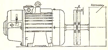
Rice. 1. Align the two shafts with clamps attached to the ends of the shafts
If the electric motor is connected to the mechanism through a gear wheel, then a prerequisite for the correct inclusion is: parallelism of the shafts and normal transmission of the gears. The correct position of the shafts is determined by gauges consisting of steel strips of different thicknesses. If the clearances between the teeth of the gear on one side and on the other side are the same, then the connection is correct. Next, the gear clutch is checked. To do this, cut paper with a width equal to the width of the gear and a length greater than the circumference of the gear. The gear teeth are coated with paint. A strip of paper is pushed between the teeth of the gear and one of the shafts is slowly turned until the strip of paper passes between all the teeth. From the imprints left by the ink on the tape, it is determined how the engagement occurs and the mechanism or electric motor is adjusted accordingly.
Installation of ballasts on cranes
Kits of standard resistor boxes, assembled at installation, are stacked on top of each other. The number of floors of these boxes is not recommended more than 3 — 4, in order to avoid an unacceptable (increase in temperature of the upper boxes. To save non-ferrous metals, resistances should be located closer to the controllers than heating parts.
The best place to install the resistors is on the outside of the cab or on the platform above the cab. In heavy crane installations, a separate floor is usually provided to accommodate a large number of resistors. The resistor boxes are fixed to a stable metal frame with at least four bolts.
The wires are routed to the resistance boxes so that the high temperature does not destroy the insulation of the wires. To do this, it is recommended that the part of the wiring near the resistors be done with bare busbars or bare cable. Sections of bare busbars or wires are firmly fixed at both ends: at the input terminals of the resistors and at the point of transition to the insulated wire. To protect service personnel from contact, the resistance boxes are protected by sheet metal covers with ventilation holes.
Installation of brake electromagnets on cranes
The brake electromagnets obtained after the overhaul are installed in a suitably prepared place and securely fastened. The brake lever is attached to the anchor through specially provided holes in it. The connection of the armature to the brake should ensure a smooth descent and ascent of the brake pads.
When installing an electromagnet, it is recommended that the armature stroke be adjusted to a value equal to 2/3 of the maximum stroke indicated in the technical data tables. This is due to the fact that when the brake pads are actuated, the stroke of the armature may exceed the maximum value, due to which the traction force will decrease and be insufficient to release the brake disc.
Installing controllers
Factory-supplied drawings usually show the location in the cab where drum or cam controllers will be installed. To eliminate the vibration of the controller parts, as well as to prevent the wires from breaking and loosening the contact connections, the controllers must be firmly fixed to the floor or structures. Installed controllers are checked for plumb and level.
Installation of protective panels
Protective panels are installed on one side of the cabin when entering it. For the convenience of wiring, it is recommended to leave gaps of 100 — 150 mm between the panel and the cabin wall. Before the final fixing of the panel, it is necessary to check the correct positioning in the horizontal and vertical direction.
Setting the limit switches
To set the limit switch correctly, you need to know the stopping distance. They are usually reported by faucet manufacturers. If these data are not available, they must be determined empirically. For example, to determine the braking distance of the bridge mechanism, a crane is brought to the middle of the span and a mark is made at a certain distance from it on the sediment of the crane.Then the electric motor of the bridge movement mechanism turns on and when it approaches the mark, it turns off. Furthermore, movement occurs when braking, and the distance traveled from the mark to the full stop of the crane is the braking distance. Braking distance is empirically determined several times — with and without load.
Switching off the electric motor of the mechanism must take place at a distance to the limiter equal to at least half of the braking distance. In all cases, the limit bars and limit switches are installed so as to ensure reliable stopping of the bridge or trolley at least 200 mm from the limit stop.
Braking paths and other mechanisms are determined in a similar way. Boundary strips are made in workshops, mainly from uneven steel angle. The broad side of the ruler is used to directly impact the shift lever. When determining the width of the ruler, the transverse movement of the mechanism is taken into account, i.e. the displacement of the bridge or bogie from the center of the axles of the guides or crane tracks. The length and location of the limit switches of the limit switches are chosen so that the bridge or trolley stops at certain points.
The limit switch lever should not return to its original position with a straight edge. To comply with this condition, the rulers are installed in such a way that its broad side coincides with the axis of the upper part of the shift lever. The limit bars of crane bridges are attached to the crane girders or to the end wall of the building.
For ease of installation, install the limit switches first and then the risers.The installation of the crane lift limit switch is shown in fig. 2.
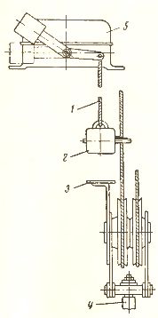
Rice. 2. Installation diagram of the limit switch for limiting the lifting of the hook: 1 — cable, 2 — counterweight, 3 — protrusion, 4 — hook, 5 — limit switch.
The switch is mounted on the trolley structure. When mounting the counterweight, it is necessary to accurately select the length of the cable on which it is suspended, so that this length is at least 200 mm to the upper stop of the trolley. Limit switches for interlocks are installed depending on the purpose — in the stairwell or on the doors.
Installation of electric wires on cranes
The installation of electrical wiring for faucets has a lot in common with installation in other electrical installations, but the requirements for wiring faucets in some cases increase.