Complete switchgear and transformer substations in urban power transmission networks
 In urban electrical networks, complete distribution units (KRU) have found wide application. They make it possible to reduce the time required for the construction of substations, to carry out their construction by industrial methods, to introduce maximum substations, as well as to ensure convenient and safe work.
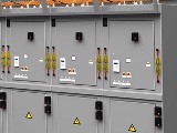
In urban TP and RP, they are mainly used complete one-sided service switchgear, type KSO (Fig. 1); versions KSO-2UM: KSO-266 and KSO-366, which have different filling schemes with equipment. Cameras of the KSO-2UM series (see Fig. 1, a) are equipped with a blocking device between the switch and the disconnector, but they do not have stationary grounding knives, which are available in the new KSO-266 type cameras (see Fig. 1, b) and KSO-272 (Fig. 2).
Rice. 1.Cameras type KSO: a — series KSO -2UM; b — series KSO -266; 1 — mesh door; 2 — bus disconnector; 3 — drives of bus and line disconnectors; 4 — circuit breaker drive; 5 — current transformer; 6 — linear disconnector; 7 — oil switch VMP -10; 8 — upper massive door; 9 — lower door; 10 — grounding disconnector; 11 — drive of the earthing disconnector; 12 — phase hatch; 13 — light cornice.
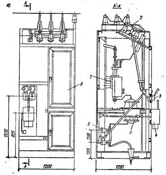
Unlike the previously used cameras in KSO -272, busbar and line disconnectors have ground blades (bus disconnectors RVFZ, cable disconnectors — RVZ). To avoid wrong operations during maintenance and repair, mechanical locks are provided in the cameras.
To complete the switchgear of substations, they also produce KSO-366 cameras with fully installed devices and switching devices. KSO-366 cameras differ from KSO-266 cameras by the presence of an inventory insulating partition, which, for safety reasons during the production of work, is installed in special channels, which prevents the door from closing.
Rice. 2. Camera KSO -272: 1.5 — drives of bus and line disconnectors; 2 — drives of grounding knives; 3 — protective fence; 4 — light cornice; 6 — spring drive PPV -10; 7, 11 — bus and line disconnectors; 8 — knives for grounding; 9-switch VPMP-10; 10 — current transformers
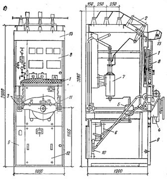
Application of entire transformer substations (KTP) in urban electrical networks is technically feasible and economically justified.Of the available KTP designs, the most widespread in urban electrical networks are KTPN-66 external installation with external service and BKTPU external installation with internal service. Transformer substations KTPN-66 (Fig. 3, a) are designed for connection to air or cable networks with voltages of 6 and 10 kV. With cable input dead-end and transit connection is possible, with air-only dead-end.
The 6-10 kV switchgear is separated from the transformer room by a metal partition. The low voltage switchboard (400/230 V) is externally controlled.
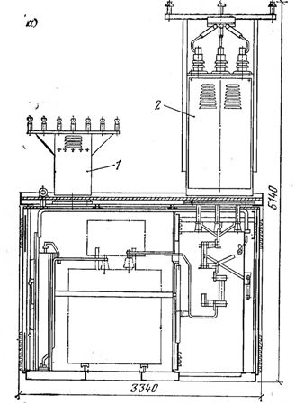
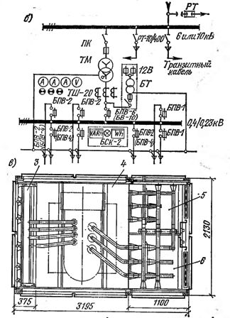
Rice. 3. Complete transformer substation for outdoor installation of the KTPN-66 series with one transformer with a capacity of up to 400 kVA. a — section; b — switching circuit; in — plan; 1 — portal for low voltage; 2 — portal for high voltage (6 or 10 kV); 3 — shield 400/230 v; 4 — power transformer chamber; 5 — line output cell: 6 — transformer input cell
The dimensions of the transformer chamber allow one transformer with a capacity of up to 630 kVA to be installed in it. Air inlet substations are fitted with ports 1 and 2, which are not available for cable inlet substations. In the KTPN-66 circuits (see Fig. 3, b), connected to overhead lines with a voltage of 6-10 kV, protection against atmospheric overvoltage is provided by limiters RT.
Transformer substations of the BKTP type are manufactured in plants from volumetric reinforced concrete blocks of two types. Unit 1 forms the transformer room and Unit 2 is the switchgear room. The blocks are assembled from vibro-rolled parts with a thickness of about 90 mm.The electrical equipment of units No. 1 and 2, except for the power transformer, has been completed at the factory. Assembled blocks are delivered to the site and installed on a prepared base.
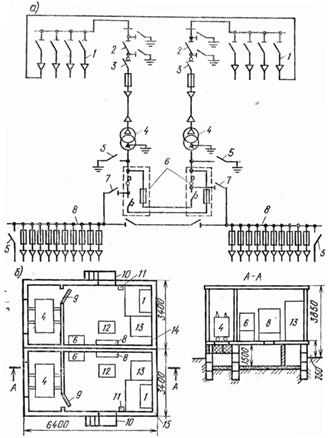
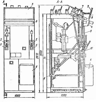
Rice. 4. Complete transformer substation of reinforced concrete volume elements of BKTPU: a — electrical diagram; b — location plan; 1-nodes 6-10 kV with single-pole disconnectors; 2 — three-pole disconnector; 3 — load switch; 4 — power transformers; 5 — overlays for grounding; 6 — contactor stations; 7 — breakers for 1000 A; 8 — assemblies with fuses and output cables up to 1000 V; 9 — mesh doors; 10 — stairs; 11 — dashboard for own needs; 12 — hatch; 13 — camera KSO -366; 14, 15 — volumetric blocks
BKTP transformer substations are used in the form of single-transformer or two-transformer substations with transformers with a capacity of up to 400 kVA. Switchgears for 6-10 kV BKTP are five connections with single-pole disconnectors, and for 400/230 V-distribution panel ShchOB-59, consisting of seven blocks of the BPV-2, BPV-4 series and automatic switching stations.
The substation BKTPU for two transformers of 630 kV-A each (Fig. 4, a, b) consists of two volumetric reinforced concrete blocks 14 and 15, manufactured at the plant, in which switchgear and power transformers are placed 4. In each block , mounted from vibratory roller plates with a thickness of 8.8 cm, electrical equipment is installed at the plant (except for power transformers), and then, with the help of trailers with a load capacity of 20 tons, they are delivered to the installation of the substation site. The mass of a fully assembled unit without a transformer is about 19 tons.
The external surfaces of the substation are painted, the doors are steel.Previously, at the place of installation of the substation, a foundation of reinforced concrete slabs or bricks is erected, on which the substation is then placed. Power transformers are supplied separately and installed later.
The use of the BKTPU substation allows its construction and installation by an industrial method.
The BKTPU substation can be used as a single transformer. In this case, a foundation is built and a block is placed on it, followed by the installation of a power transformer in it. BKTPU transformer substations are stationary. If necessary, they are supplemented with another reinforced concrete block, which is a distribution system with a voltage of up to 1000 V for street lighting.
The electrical circuit of the BKTPU for two transformers is two-beam. The 6-10 kV switchgear is a unit designed for four connections with single-pole disconnectors.
For the possibility of disconnecting a power transformer with a capacity of 630 kVA, a VNRp-10 / 400-10z load switch is installed in the KSO-366 chamber. In the same chamber, a three-pole disconnector 2 with grounding blades is installed, when it is turned on, it is possible to carry out repair work on the equipment without portable grounding. On the voltage side of the transformer up to 1000 V there are also strips 5 for grounding.
The switchgear with a voltage of up to 1000 V is a set for connecting ten cable outgoing lines with mounted fuses PN-2rated for current: in two lines of 250 A, six lines of 400 A and two lines of 600 A. This installation has 5 earthing pads. The 6 contactor stations are installed for a working current of 1000 A.
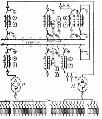
Rice. 5.Scheme of a two-room RP combined with a transformer substation for two transformers with a power of 630 kVA each
The power transformer 4 is enclosed from the switchgear by a concrete partition with a normally closed mesh door 9. To cool the transformer, ventilation holes are provided in the base, doors and above the doors. Metal stairs 10 are installed at the entrance doors. In the electrical networks of large cities, two-sided transformer substations are used, combined with a transformer substation designed for two transformers with a capacity of 630 kV-A each (Fig. 5) .