Installation of frequency converters
 Installation, adjustment and maintenance of the frequency converter should only be carried out by qualified technical personnel. Rough handling may damage the inverter. Do not drop the inverter, subject it to shock or impact while carrying it.
Safety instructions for installing the frequency converter (DANFOSS frequency converter instructions are used):
1. Touching live parts can be fatal, even if the equipment is disconnected from the mains. When working with live parts, make sure that the voltage inputs are disconnected: both from the mains and from any other (connecting the DC intermediate circuit), the motor cable is disconnected (if the motor is rotating).
Note that high DC link voltages may still exist even if the LEDs are off. Wait at least 4 minutes before touching potentially dangerous live parts of drives up to and including 7.5 kW. Wait at least 15 minutes before working on drives above 7.5 kW.
2. Frequency converter must be properly grounded. Ground leakage current exceeds 3.5 mA. It is prohibited to use the neutral wire as grounding.
3. The [OFF] button on the control panel does not function as a safety switch. It does not disconnect the frequency converter from the mains and does not guarantee a power failure between the frequency converter and the motor.
Checking the compatibility of the components before starting the installation.
1. Check the transmitter code number with the one you ordered.
 2. Check that the input voltage indicated on the adjustable frequency drive matches the voltage of the mains you plan to connect to. If the mains voltage is lower than the input voltage of the frequency converter, the device will operate with reduced performance or will operate with an error. It is not allowed to connect the device to an electrical supply with a voltage higher than the input voltage of the inverter indicated on the data plate!
3. Check that the rated voltage of the motor does not exceed the output voltage of the frequency converter. The nominal voltage of the motor is in most cases determined by the connection diagram, so check whether the motor is connected in star or delta and what voltage values correspond to this connection diagram (indicated on the motor nameplate).
4. The rated current of the motor should not exceed the rated output current of the frequency converter in most cases, otherwise the drive will not be able to develop the rated torque.
Check the installation conditions of the frequency converter.
2. The installation site must be dry (maximum relative humidity 95%, non-condensing).
3. Ambient operating temperature 0–40 ° C. At temperatures from -10 to 0 ° C and above +40 ° C, reduced performance will occur. It is not recommended to use the frequency converter at temperatures below -10 and above +50 ° C, as this may lead to a reduction in the service life of the product.
4. The maximum installation height of the device above sea level for operation without reduction is 1000 m.
5. Check if it is possible to ventilate the frequency converter. Wall-to-wall mounting of converters is allowed (IP 20 and 54 cabinets), but 100 mm air space must be provided at the top / bottom of the unit for frequency converters up to 30 kW, 200 mm for frequency converters from 30 to 90 kW and 225 mm for a power of 90 kW.
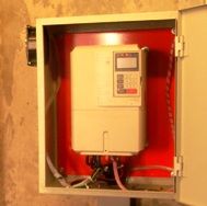
The inverter heats up during operation, so the free space around the inverter should be at least 10 cm and provide air circulation and cooling. The surface on which the inverter is mounted must be made of non-flammable material and have sufficient mechanical strength to support the weight of the inverter.
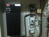
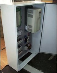
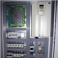
When installing the inverter in a cabinet, attention should be paid to the cooling efficiency.Make sure the airflow from the cabinet fan is as close to the inverter as possible. An example of the location of the converter in the cabinet is shown in figure 3.1.
The converter must be located so that it does not fall into the air flow of other converters and heat-generating elements of other equipment, including braking resistors. It is recommended to avoid placing one converter on top of another or to maintain a minimum distance between blocks of 300 mm. An example of the location of several converters in a cabinet is shown in Figure 1.
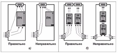
Figure 1 — Examples of placement in the cabinet: a) one converter; b) multiple converters
The forced cooling fan of the cabinet must be installed to achieve maximum airflow around the inverter. To prevent the recirculation of heated air from outside and inside the cabinet, it is recommended to install reflective screens.
Electrical connections
2. Each actuator must be grounded separately, and the length of the grounding line must be as short as possible. The recommended cross-section of the grounding cables must be the same cross-section as the wires of the supply network. During installation, connect the ground wire first.
3. Input fast-acting fuses need to be installed (specify fuse brands in design guides). Fuse ratings can be found in the technical data table.
4.Separate conduits should be used for input power cables, output power cables and control cables.
5. Use shielded cables to meet EMC requirements. Protect control cables from electromagnetic interference.
6. Check the correct connection of the input (terminals L, N for single-phase network and L1, L2, L3 for three-phase) and output power wires (terminals U, V, W).
7. The connection to the PE terminal of the inverter is made with a ground wire. Do not use neutral as a ground wire. Combining grounding and neutral can only be done at the physical grounding point.
Checking the correct connection of the motor.
1. The maximum EMC-free length of the unshielded motor cable is up to 50 m. The desired EMC standards can be achieved with built-in or external filters and shielded cable. Please refer to the design guides for the maximum cable length depending on the environmental category environment.
2. According to the standards adopted on the territory of the Russian Federation, the frequency converter as an independent product may have a different EMC class. However, GOST 51524-99 for electric drive (electric drive is a whole product — a combination of frequency converter, electric motor and load) prescribes class A1 / B, which is achieved only when using shielded cables and an improved RF filter (for Danfoss converters , built into the inverter)
3. No capacitor banks should be connected to the supply circuit between the drive and the motor to compensate for reactive power.
4.Two-speed motors, wound-rotor motors, and motors that have previously been run in a star or delta circuit must be permanently connected to one operating circuit and at one speed.
5. If there is a contactor or circuit breaker in the circuit between the drive and the motor, the corresponding signal of its position must reach the drive. It is not allowed to break the circuit with a contactor when working on a frequency converter or magneto motor. If the motor is equipped with a brake, a control signal must be provided to match its operation with the inverter. Do not power the brake from the converter supply.
6. If the engine is equipped with forced ventilation, it must be provided for its activation with the engine running.
7. If the motor is equipped with a temperature sensor (thermistor), then it is recommended to feed this signal to the frequency converter for the possibility of emergency shutdown of the electric motor in case of overheating.