Basics of electricity
 The ancient Greeks observed electrical phenomena long before the study of electricity began. It is enough to rub the semi-precious amber stone with wool or fur, as it begins to attract pieces of dry straw, paper or fluff and feathers.
Modern school experiments use glass and ebonite rods rubbed with silk or wool. In this case, it is considered that a positive charge remains on the glass rod, and a negative charge on the ebonite rod. These rods can also attract small pieces of paper or the like. small objects. It is this attraction that is the electric field effect that was studied by Charles Coulomb.
In Greek, amber is called electron, so to describe such an attractive force, William Hilbert (1540 - 1603) proposed the term "electric".
In 1891, the English scientist Stony George Johnston hypothesized the existence of electrical particles in substances, which he called electrons. This statement made it much easier to understand electrical processes in wires.
Electrons in metals are quite free and easily separated from their atoms, and under the action of an electric field, more precisely, potential differences move between metal atoms, creating electricity… Thus, the electric current in a copper wire is a flow of electrons flowing along the wire from one end to the other.
Not only metals are capable of conducting electricity. Under certain conditions, liquids, gases and semiconductors are electrically conductive. In these environments, charge carriers are ions, electrons, and holes. But for now we are only talking about metals, because even in them everything is not so simple.
For now, we are talking about direct current, the direction and magnitude of which do not change. Therefore, on electrical diagrams it is possible to indicate with arrows where the current flows. Current is believed to flow from the positive pole to the negative pole, a conclusion reached early in the study of electricity.
Later it turned out that the electrons actually move in the exact opposite direction — from minus to plus. But despite this, they did not give up the "wrong" direction, moreover, this very direction is called the technical direction of the current. What difference does it make if the lamp still lights up. The direction of motion of the electrons is called true and is most often used in scientific research.
This is illustrated in Figure 1.
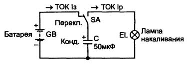
Picture 1.
If the switch is "thrown" to the battery for some time, the electrolytic capacitor C will be charged and some charge will accumulate on it. After charging the capacitor, the switch was turned to the bulb. The lamp blinks and goes out - the capacitor discharges. It is quite obvious that the duration of the flash depends on the amount of electric charge stored in the capacitor.
A galvanic battery also stores electric charge, but much more than a capacitor. Therefore, the flash time is long enough — the lamp can burn for several hours.
Electric charge, current, resistance and voltage
The study of electric charges was carried out by the French scientist C. Coulomb, who in 1785 discovered the law named after him.
In formulas, electric charge is denoted as Q or q. The physical meaning of this quantity is the ability of charged bodies to enter into electromagnetic interactions: as charges repel, different ones attract. The force of interaction between charges is directly proportional to the size of the charges and inversely proportional to the square of the distance between them. If it is in the form of a formula, it looks like this:
F = q1 * q2 / r2
The electric charge of the electron is very small, so in practice they use the magnitude of the charge called the coulomb... It is this value that is used in the international system SI (C). A pendant contains no less than 6.24151 * 1018 (ten to the eighteenth power) electrons. If 1 million electrons per second are released from this charge, then this process will last up to 200 thousand years!
The unit of measurement of current in the SI system is the Ampere (A), named after the French scientist Andre Marie Ampere (1775 — 1836). At a current of 1A, a charge of exactly 1 C passes through the cross section of the wire in 1 second. The mathematical formula in this case is as follows: I = Q / t.
In this formula, current is in amperes, charge is in coulombs, and time is in seconds. All devices must conform to the SI system.
In other words, one pendant is released per second. Very similar to the speed of a car in kilometers per hour.Therefore, the strength of an electric current is nothing more than the rate of flow of electric charge.
More often in everyday life, the off-system unit Ampere * hour is used. It is enough to recall car batteries, the capacity of which is indicated only in ampere-hours. And everyone knows and understands this, although no one remembers any pendants in auto parts stores. But at the same time there is still a ratio: 1 C = 1 * / 3600 amperes * hour. It is possible to call such a quantity ampere * second.
In another definition, a current of 1 A flows in a conductor of resistance 1 Ω at potential difference (voltage) at the ends of the wire 1 V. The ratio between these values is determined by Ohm's Law... This is perhaps the most important electrical law, it is not by chance that folk wisdom says: «If you do not know Ohm's law, stay home!»
The Ohm's Law Test
This law is now known to everyone: «The current in the circuit is directly proportional to the voltage and inversely proportional to the resistance». It seems that there are only three letters — I = U / R, every student will say: «So what?». But actually the road to this short formula was quite thorny and long.
To test Ohm's law, you can assemble the simplest circuit shown in Figure 2.
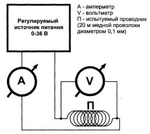
Figure 2.
The investigation is quite simple—by increasing the supply voltage point by point on the paper, construct the graph shown in Figure 3.
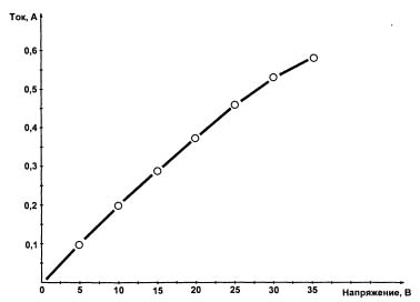
Figure 3.
It seems that the graph should turn out to be a perfectly straight line, since the relationship I = U / R can be represented as U = I * R, and in mathematics it is a straight line. In fact, on the right side, the line bends down. Maybe not much, but it bends and for some reason is very versatile.In this case, the bending will depend on the method of heating the tested resistance. It is not for nothing that it is made of a long copper wire: you can tightly wind a coil to a coil, you can close it with a layer of asbestos, maybe the temperature in the room today is the same, but yesterday it was different, or there is a draft in the room.
This is because temperature affects resistance in the same way as the linear dimensions of physical bodies when heated. Each metal has its own temperature coefficient of resistance (TCR). But almost everyone knows and remembers about expansion, but forget about the change in electrical properties (resistance, capacitance, inductance). But temperature in these experiments is the most stable source of instability.
From a literary point of view, it turned out to be a rather beautiful tautology, but in this case it very accurately expresses the essence of the problem.
Many scientists in the middle of the 19th century tried to discover this dependence, but the instability of the experiments interfered and raised doubts about the truth of the results obtained. Only Georg Simon Ohm (1787-1854) succeeded in this, who managed to reject all side effects or, as they say, to see the forest for the trees. The 1 Ohm resistance still bears the name of this brilliant scientist.
Each ingredient can be expressed by Ohm's law: I = U / R, U = I * R, R = U / I.
In order not to forget these relationships, there is the so-called Ohm's Triangle, or something similar, shown in Figure 4.
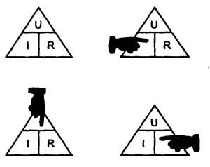
Figure 4. Ohm's triangle
Using it is very simple: just close the desired value with your finger and the other two letters will show you what to do with them.
It remains to recall what role tension plays in all these formulas, what is its physical meaning. Voltage is usually understood as the potential difference at two points in the electric field. For easier understanding, they use analogies, as a rule, with a tank, water and pipes.
In this "plumbing" scheme, the consumption of water in the pipe (liters / sec) is only the current (coulomb / sec), and the difference between the upper level in the tank and the open tap is the potential difference (voltage). Also, if the valve is open, the outlet pressure is equal to atmospheric, which can be taken as a conditional zero level.
In electrical circuits, this convention makes it possible to take a point for a common conductor ("ground") against which all measurements and adjustments are made. Most often, the negative terminal of the power supply is assumed to be this wire, although this is not always the case.
Potential difference is measured in the volt (V), named after the Italian physicist Alessandro Volta (1745-1827). According to the modern definition, with a potential difference of 1 V, an energy of 1 J is spent to move a charge of 1 C. The consumed energy is replenished by a power source, by analogy with a «plumbing» circuit, it will be a pump that supports the water level in the tank.