Digital devices: pulse counters, encoders, multiplexers
 Pulse counter — an electronic device designed to count the number of pulses applied to the input. The number of pulses received is expressed in binary notation.
Pulse counters are a type of registers (count registers) and are built on flip-flops and logic gates, respectively.
The main indicators of the counters are the counting coefficient K 2n — the number of pulses that can be counted by the counter. For example, a four-trigger counter may have a maximum count factor of 24 = 16. For a four-trigger counter, the minimum output code is 0000, the maximum -1111, and when the count factor is Kc = 10, the output stops counting when code 1001 = 9 .
 Figure 1a shows a diagram of a four-bit T-flip counter connected in series. The count pulses are applied to the count input of the first flip-flop. The counter inputs of the following flip-flops are connected to the outputs of the previous flip-flops.
The operation of the circuit is illustrated by the timing graphs shown in Figure 1, b.When the first count pulse arrives at its decay, the first flip-flop goes into state Q1 = 1, i.e. the counter has a digital code of 0001. At the end of the second counter pulse, the first flip-flop goes to state «0», and the second goes to state «1». The counter records number 2 with code 0010.
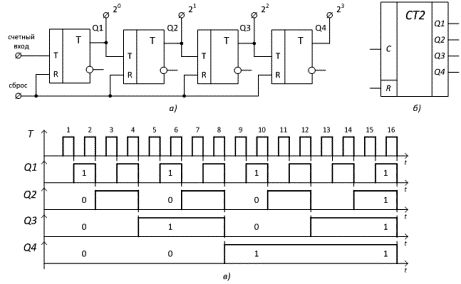
Figure 1 — Binary four-digit counter: a) diagram, b) conventional graphical representation, c) timing diagrams of operation
From the diagram (Fig. 1, b) it can be seen that, for example, according to the attenuation of the 5th pulse, code 0101 is written in the counter, according to the 9th — 1001, and so on. At the end of the 15th pulse, all bits of the counter are set to state «1», and after the decay of the 16th pulse, all triggers are reset, that is, the counter goes to its initial state. There is a «reset» input to force the counter to reset.
The count factor of a binary counter is found from the ratio Ksc = 2n, where n is the number of bits (flip-flops) of the counter.
Counting the number of pulses is the most common operation in digital information processing devices.
During the operation of the binary counter, the repetition rate of the pulses at the output of each subsequent flip-flop is reduced by half compared to the frequency of its input pulses (Fig. 1, b). Therefore, counters are also used as frequency dividers.
A scrambler (also called an encoder) converts a signal into a digital code, most often decimal numbers in a binary number system.
An encoder has m inputs numbered consecutively with decimal numbers (0, 1,2, …, m — 1) and n outputs. The number of inputs and outputs is determined by the relationship 2n = m (Fig. 2, a). The symbol «CD» is formed from the letters in the English word Coder.
Applying a signal to one of the inputs causes the output to produce an n-bit binary number corresponding to the input number. For example, when a pulse is applied to the fourth input, a digital code 100 appears at the outputs (Fig. 2, a).
Decoders (also called decoders) are used to convert binary numbers back to small decimal numbers. The inputs of the decoder (Fig. 2, b) are intended for supplying binary numbers, the outputs are sequentially numbered with decimal numbers. When a binary number is applied to the inputs, a signal appears at a particular output whose number corresponds to the input number. For example, when code 110 is provided, the signal will appear at the 6th output.
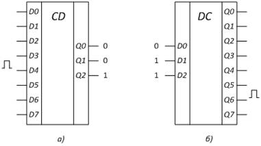
Figure 2 — a) UGO encoder, b) UGO decoder
Multiplexer - a device in which the output is connected to one of the inputs, according to the address code. Che. a multiplexer is an electronic switch or commutator.
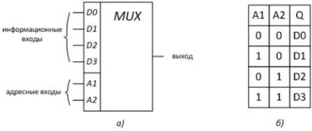
Figure 3 — Multiplexer: a) conventional graphical representation, b) state table
An address code is sent to inputs A1, A2, which determines which of the signal inputs will be transmitted to the output of the device (Fig. 3).
To convert information from digital to analog, use digital-to-analog converters (DACs), and for the reverse conversion, use analog-to-digital converters (ADCs).
The input signal of the DAC is a binary multi-digit number and the output signal is the voltage Uout formed based on the reference voltage.
The analog-to-digital conversion procedure (Fig. 4) consists of two stages: time sampling (sampling) and level quantization. The sampling process consists of measuring values of a continuous signal only at discrete times.
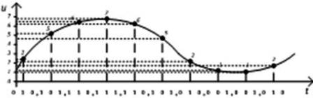
Figure 4-The analog-to-digital conversion process
For quantization, the range of variation of the input signal is divided into equal intervals — quantization levels. In our example there are eight of them, but usually there are many more. The quantization operation is reduced to determining the interval in which the sample value fell and assigning a digital code to the output value.