Microprocessor systems
 The use of microprocessor systems in almost all electrical devices is the most important feature of the technical infrastructure of modern society. Electricity, industry, transport, communication systems are highly dependent on computer control systems. Microprocessor systems are embedded in measuring instruments, electrical devices, lighting installations, etc.
All this obliges the electrical engineer to know at least the basics of microprocessor technology.
Microprocessor systems are designed to automate information processing and control various processes.
The term "microprocessor system" is very broad and includes such concepts as "electronic computing machine (ECM)", "control computer", "computer" and others.
The microprocessor system includes Hardware or in English — hardware and software (Software) — software.
Digital information
The microprocessor system works with digital information, which is a series of numerical codes.
At the core of any microprocessor system is a microprocessor that can only accept binary numbers (made up of 0s and 1s).Binary numbers are written using the binary number system. For example, in everyday life we use a decimal number system that uses ten characters or digits to write numbers, 0,1,2,3,4,5,6,7,8,9. Accordingly, in the binary system there are only two such symbols (or digits) — 0 and 1.
It is necessary to understand that the number system is only the rules for writing numbers, and the choice of the type of system will be determined by the ease of use. The choice of a binary system is due to its simplicity, which means the reliability of digital devices and the ease of their technical implementation.
Consider the units of measurement of digital information:
A bit (from the English «BInary digiT» — binary digit) takes only two values: 0 or 1. You can encode the logical value «yes» or «no», the state «on» or «off», the state «open» «or» closed «etc.
A group of eight bits is called a byte, for example 10010111. One byte allows you to encode 256 values: 00000000 — 0, 11111111 — 255.
A bit is the smallest unit of information.
Byte — the smallest unit of information processing. Byte - part of a machine word, usually consisting of 8 bits and used as a unit for the amount of information during its storage, transmission and processing on a computer. A byte serves to represent letters, syllables and special characters (usually occupying all 8 bits) or decimal digits (each 2 digits in 1 byte).
Two contiguous bytes are called a word, 4 bytes a double word, 8 bytes a quad word.
Almost all information that surrounds us is analog. Therefore, before the information enters the processor for processing, it is converted using an ADC (analog-to-digital converter).In addition, the information is encoded in a certain format and can be digital, logical, textual (symbolic), graphic, video, etc.
For example, a table of ASCII codes (from English American Standard Code for Information Interchange) is used to encode text information. One character is written in one byte, which can take 256 values. Graphical information is divided into dots (pixels), and the color and position of each dot is coded horizontally and vertically.
In addition to the binary and decimal systems, MS uses a hexadecimal system in which the symbols 0 ... 9 and A ... F are used to write numbers. Its use is due to the fact that one byte is described by a two-digit hexadecimal number, which greatly reduces record the numeric code and make it more readable (11111111 — FF).
Table 1 — Writing numbers in different number systems
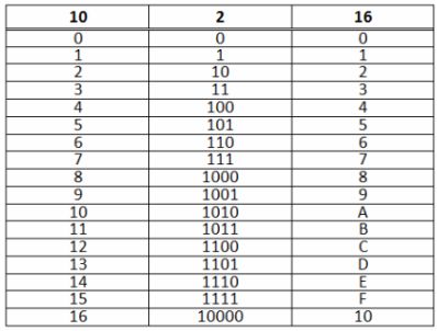
To determine the value of the number (for example, the value of the number 100 for different number systems can be 42, 10010, 25616), at the end of the number add a Latin letter indicating the number system: for binary numbers the letter b, for hexadecimal numbers — h , for decimal numbers — d. A number without an additional designation is considered a decimal.
Converting numbers from one system to another and basic arithmetic and logical operations with numbers allows you to make an engineering calculator (standard application of the Windows operating system).
Structure of a microprocessor system
The microprocessor system is based on a microprocessor (processor) that performs information processing and control functions. The rest of the devices that make up the microprocessor system serve the processor by helping it work.
Mandatory devices for creating a microprocessor system are input / output ports and partly memory... Input - output ports connect the processor to the outside world by providing information for processing and outputting the results of processing or control actions. Buttons (keyboard), various sensors are connected to the input ports; to output ports — devices that allow electrical control: indicators, displays, contactors, solenoid valves, electric motors, etc.
Memory is primarily needed to store a program (or set of programs) necessary for the processor to operate. A program is a sequence of commands that the processor understands, written by a human (usually a programmer).
The structure of a microprocessor system is shown in Figure 1. In a simplified form, the processor consists of an arithmetic logic unit (ALU) that processes digital information, and a control unit (CU).
Memory typically includes read-only memory (ROM), which is non-volatile and intended for long-term storage of information (eg, programs), and random-access memory (RAM), intended for temporary data storage.

Figure 1 — The structure of the microprocessor system
The processor, ports, and memory communicate with each other via buses. A bus is a set of wires that are functionally united. A single set of system buses is called intrasystem bus, in which there are:
-
DB data bus (Data Bus), through which data is exchanged between the processor, memory and ports;
-
address bus AB (Address Bus), used to address the memory cells and ports of the processor;
-
control bus CB (Control Bus), a set of lines that transmit various control signals from the processor to external devices and vice versa.
Microprocessors
Microprocessor — a software-controlled device designed to process digital information and control the process of this processing, made in the form of one (or several) integrated circuits with a high degree of integration of electronic elements.
A microprocessor is characterized by a large number of parameters, as it is both a complex software-controlled device and an electronic device (microcircuit). Therefore, for a microprocessor, both the case type and the instruction set for the processor… The capabilities of a microprocessor are defined by the concept of microprocessor architecture.
The prefix «micro» in the name of the processor means that it is implemented using micron technology.
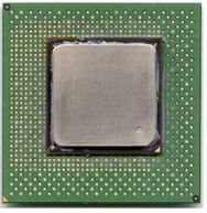
Figure 2 — External view of the Intel Pentium 4 microprocessor
During operation, the microprocessor reads program commands from memory or an input port and executes them. What each command means is determined by the processor's instruction set. The instruction set is built into the architecture of the microprocessor, and the execution of the command code is expressed in the execution of certain micro-operations by the internal elements of the processor.
Microprocessor architecture — this is its logical organization; it defines the capabilities of the microprocessor in terms of hardware and software implementation of the functions required to build a microprocessor system.
Main characteristics of microprocessors:
1) Clock frequency (unit of measurement MHz or GHz) — the number of clock pulses in 1 second.The clock pulses are generated by a clock generator, which is usually located inside the processor. Because all operations (instructions) are performed in clock cycles, then the work performance (the number of operations performed per unit time) depends on the clock frequency. The processor frequency may vary within certain limits.
2) Bit processor (8, 16, 32, 64 bits, etc.) — specifies the number of bytes of data processed in one clock cycle. The bit width of a processor is determined by the bit width of its internal registers. A processor can be 8-bit, 16-bit, 32-bit, 64-bit, etc. ie. data is processed in chunks of 1, 2, 4, 8 bytes. It is clear that the greater the bit depth, the higher the work productivity.
Internal architecture of the microprocessor
A simplified internal architecture of a typical 8-bit microprocessor is shown in Figure 3. The structure of the microprocessor can be divided into three main parts:
1) Registers for temporary storage of commands, data and addresses;
2) Arithmetic logic unit (ALU) which performs arithmetic and logical operations;
3) Control and timing circuit — provides command selection, organizes the operation of the ALU, provides access to all microprocessor registers, perceives and generates external control signals.
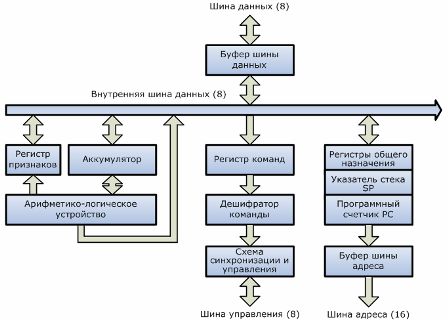
Figure 3 — Simplified internal architecture of an 8-bit microprocessor
As you can see from the diagram, the processor is based on registers, which are divided into special (with a specific purpose) and general purpose registers.
Program counter (computer) — a register containing the address of the next command byte. The processor needs to know which command will be executed next.
Battery — a register used in the majority of instructions for logic and arithmetic processing; it is both the source of one of the bytes of data that is required for the ALU operation and the place where the result of the ALU operation is placed.
A function register (or flag register) contains information about the internal state of the microprocessor, specifically the result of the last ALU operation. A flag register is not a register in the usual sense, but simply a set of flip flops (flag up or down. There are usually zero, overflow, negative and carry flags).
Stack Pointer (SP) — keeps track of the position of the stack, that is, it contains the address of its last used cell. Stack — a way of organizing data storage.
A command register contains the current command byte being decoded by the command decoder.
The external bus lines are isolated from the internal bus lines by buffers, and the main internal elements are connected by a high-speed internal data bus.
To improve the performance of a multiprocessor system, the functions of the central processor can be distributed among several processors. To help the central processor, the computer often introduces co-processors, focused on the efficient execution of any specific functions. Widespread mathematical and graphic co-processors, input and output offloading the central processor from simple but numerous operations of interaction with external devices.
At the current stage, the main direction of increasing productivity is the development of multi-core processors, i.e. combining two or more processors in one case to perform several operations in parallel (simultaneously).
Intel and AMD are the leading companies for designing and manufacturing processors.
Microprocessor system algorithm
Algorithm — a precise prescription that uniquely sets the process of transforming the initial information into a sequence of operations that allow solving a set of tasks of a certain class and obtaining the desired result.
The main control element of the entire microprocessor system is a processor... It, with the exception of a few special cases, controls all other devices. The remaining devices, such as RAM, ROM and I / O ports, are subordinate.
As soon as it is turned on, the processor starts reading digital codes from the memory area that is reserved for storing programs. Reading is done sequentially cell by cell, starting from the very first one. A cell contains data, addresses, and commands. An instruction is one of the elementary actions that a microprocessor can perform. All the work of the microprocessor is reduced to sequential reading and execution of commands.
Consider the sequence of actions of the microprocessor during the execution of program commands:
1) Before the next instruction is executed, the microprocessor stores its address in the computer program counter.
2) The MP accesses the memory at the address contained in the computer and reads from the memory the first byte of the next command in the command register.
3) The command decoder decodes (deciphers) the command code.
4) In accordance with the information received from the decoder, the control unit generates a time-ordered sequence of micro-operations that execute the command instructions, including:
— retrieves operands from registers and memory;
— performs arithmetic, logical or other operations on them as prescribed by the command code;
— depending on the length of the command, changes the contents of the computer;
— transfers control to the next command whose address is again in the computer program counter.
The instruction set for a microprocessor can be divided into three groups:
1) Commands to move data
The transfer takes place between memory, processor, I / O ports (each port has its own address), between processor registers.
2) Data transformation commands
All data (text, picture, video, etc.) are numbers, and only arithmetic and logical operations can be performed with numbers. Therefore, the commands of this group include addition, subtraction, comparison, logical operations, etc.
3) Transfer of control command
It is very rare for a program to consist of a single sequential instruction. Most algorithms require program branching. In order for the program to change the algorithm of its work, depending on any condition, control transfer commands are used. These commands ensure the flow of program execution along different paths and organize loops.
External devices
External devices include all devices that are external to the processor (except RAM) and connected through I / O ports. External devices can be classified into three groups:
1) human-computer communication devices (keyboard, monitor, printer, etc.);
2) devices for communication with control objects (sensors, actuators, ADC and DAC);
3) external storage devices with large capacity (hard disk, floppy disks).
External devices are connected to the microprocessor system physically — through connectors and logically — through ports (controllers).
An interrupt system (mechanism) is used to interface between the processor and external devices.
Interrupt system
This is a special mechanism that allows at any time, through an external signal, to force the processor to stop the execution of the main program, perform operations related to the event that caused the interruption, and then return to the execution of the main program.
Every microprocessor has at least one interrupt request input INT (from the word Interrupt).
Let's consider an example of the interaction of a personal computer processor with a keyboard (Figure 4).
Keyboard — a device for entering symbolic information and control commands. To connect the keyboard, the computer has a special keyboard port (chip).

Figure 4 — CPU operation with the keyboard
Algorithm of work:
1) When a key is pressed, the keyboard controller generates a numeric code. This signal goes to the keyboard port chip.
2) The keyboard port sends an interrupt signal to the CPU. Each external device has its own interrupt number by which the processor recognizes it.
3) After receiving an interrupt from the keyboard, the processor interrupts the execution of the program (for example, the Microsoft Office Word editor) and loads the program for processing keyboard codes from memory. Such a program is called a driver.
4) This program directs the processor to the keyboard port and the numeric code is loaded into the processor register.
5) The digital code is stored in memory and the processor continues to perform another task.
Due to the high speed of operation, the processor executes a large number of processes simultaneously.