The use of microprocessor systems in electrical engineering on the example of the use of PLC
 Talk about the app microprocessor systems, that means talking about almost all the technical devices that surround us. In every field of electrical engineering: in power supply, electric drive, electric lighting, they are used from the simplest circuits under the control of 8-bit microcontrollers to the most complex microprocessor systems with multi-level network control.
I am paying attention to programmable controllers (PLC) (also called programmable relays) LOGO! Siemens is designed to build the simplest automatic control devices. Why LOGO! Siemens? Because working with it does not require special knowledge of microprocessor technology and programming languages, but enough fundamentals of electrical engineering and digital electronics (also basics). In addition, Siemens software products are freely available.
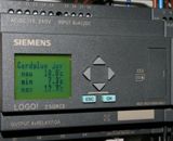
Figure 1 shows the appearance of the LOGO! Main and expansion module.The module operation algorithm is set by a program composed of a set of built-in functions — FBD (Function Block Diagram) — a graphical programming language. The modules can be programmed either from a computer equipped with LOGO Soft Comfort or by installing a programmed memory module or from their keyboard (if available) without using additional software.
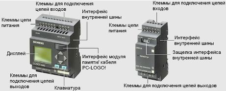
Figure 1 — The design of LOGO! Main and expansion module
The cost of the controller and expansion modules is not high, which makes it possible to use them even for automation and simple processes.
Take an example from Siemens itself, a mixer. Figure 3.13 shows a block diagram of the mixing device.
Assignment Statement:
At the start command (SB1), open valve Y1 and fill the tank to level SL2. Close valve Y1, open valve Y2 and fill the tank to mark SL1. Close valve Y2 and run the mixer for 15 minutes. Open valve Y3 and drain the mixture. On the signal from the SL3 sensor, close the Y3 valve and reset the circuit.
Executive devices:
-
M — mixer motor
-
Y1 — component 1 supply valve
-
Y2 — valve for component 2
-
Y3 — discharge valve for ready mixture
Sensors and manual control:
-
SL1 — tank full sensor
-
SL2 — component 1 tank fill sensor
-
SL3 — empty tank sensor
-
SB1 — button to start the installation
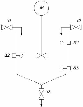
Figure 2 — Block diagram of the mixing device
Based on the specifications, we will prepare a classic relay-contactor circuit (Figure 3). Traditionally, we set the Stop button SB1, so the button to start the installation becomes SB2.
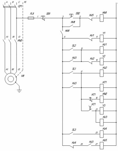
Figure 3 — Relay-contactor circuit of the mixing device
The same scheme implemented on LOGO! (Figure 4). It's definitely easier, but only a small part of the controller's capabilities are used. In addition to the controller itself, the chain of elements contains only sensors, controls and drives. This means that the chain is much more reliable than its classic counterpart.
The marking of the LOGO! 230RC indicates: supply voltage — 115-240 V DC or AC, relay outputs (load current — 3 A for inductive load).
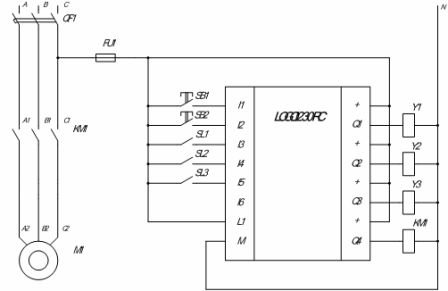
Figure 4 — Diagram of the LOGO! mixer.
To program the PLC LOGO! it is necessary to create a circuit program. Creating a circuit program with LOGO! Soft Comfort, the LOGO! programming tool used to create, test, change, save and print circuit programs easily and quickly.
LOGO! there are inputs and outputs. Inputs are identified by the letter I and a number. Outputs are identified by the letter Q and a number.
Digital inputs and outputs can be set to «0» or «1». «0» means no voltage at the input; «1» means that it is.
The block in LOGO! It is a function that converts input information to output information.
Figure 5 shows a variation of the circuit diagram of the mixer controller created in the LOGO! Soft Comfort. When we create a circuit program, we connect the connecting elements to the blocks. The simplest blocks are logical operations… Also, the circuit uses flip-flops and a turn-off delay block.
The switching program reflects the algorithm (logic) of the control circuit. The graphically implemented diagram of standard blocks and connectors is further transformed into the logical structure of the controller.
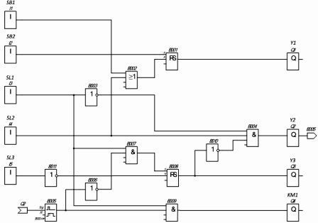
Figure 5 — Connection diagram of the LOGO! mixer.