Ammeter and voltmeter switching circuit
 In ammeters, the current flowing through the device creates a torque that causes the moving part to deflect at an angle that depends on that current. This deflection angle is used to determine the current value of the ammeter.
To measure the current in some type of energy receiver with an ammeter, it is necessary to connect the ammeter in series with the receiver so that the current of the receiver and the ammeter are the same. The resistance of the ammeter should be small compared to the resistance of the receiver of energy with which it is connected in series, so that its inclusion has practically no effect on the magnitude of the current of the receiver (on the mode of operation of the circuit). Thus, the resistance of the ammeter must be small, and the lower it is, the greater its rated current. For example, at a rated current of 5 A, the resistance of the ammeter is ra = (0.008 — 0.4) ohm. With a low resistance of the ammeter, the power losses in it are also small.
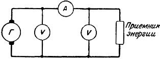
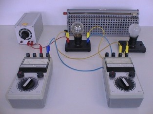
Rice. 1. Ammeter and voltmeter connection scheme
At a rated ammeter current of 5 A, the power dissipation Pa = Aza2r = (0.2 — 10) VA... The voltage applied to the terminals of the voltmeter causes a current in its circuit. At direct current it depends only on the voltage, i.e. Iv = F (Uv). This current passing through the voltmeter, as well as in the ammeter, causes its movable part to deflect at an angle which depends on the current. In this way, each value of the voltage at the terminals of a voltmeter will be well-defined values of the current and the angle of rotation of the movable part.
To determine the voltage at the terminals of the energy receiver or generator according to the readings of the voltmeter, it is necessary to connect its terminals to the terminals of the voltmeter so that the voltage of the receiver (generator) is equal to the voltage of the voltmeter (Fig. 1) .
The resistance of the voltmeter should be large compared to the resistance of the energy receiver (or generator), so that its inclusion does not affect the measured voltage (on the mode of operation of the circuit).
An example. A voltage U= 120 V is applied to the terminals of the circuit with two series-connected receivers (Fig. 2) having resistance r1=2000 ohms and r2=1000 ohms.
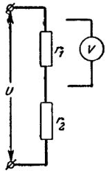
Rice. 2. Scheme for switching on the voltmeter
In this case, at the first receiver the voltage U1= 80 V, and at the second U2 = 40 V.
If you connect a voltmeter with a resistance in parallel with the first receiver rv =2000 ohms to measure the voltage at its terminals, then the voltage of both the first and the second receiver will have a value of U'1=U'2= 60 V.
Thus, turning on the voltmeter caused the voltage of the first receiver to change with U1 =80 V to U'1= 60 V, the error in measuring the voltage due to turning on the voltmeter is equal to ((60V — 80V) / 80V) x 100% = - 25%
Thus, the resistance of the voltmeter must be greater, and the greater it is, the greater its rated voltage. At a nominal voltage of 100 V, the resistance of the voltmeter rv = (2000 — 50,000) ohms. Due to the high resistance of the voltmeter, the power losses in it are low.
At a voltmeter rated voltage of 100 V the power dissipation Rv = (Uv2/ rv) What.
It follows from the above that the ammeter and the voltmeter can have measuring mechanisms on the same device, differing only in their parameters. But the ammeter and the voltmeter are included in the measured circuit in different ways and have different internal (measuring) circuits.