Transmission of energy over a wire
 An electrical circuit consists of at least three elements: a generator, which is a source of electrical energy, receiver of energy and wires connecting the generator and the receiver.
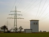
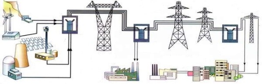
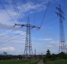
Power plants are often located far from where electricity is consumed. An overhead power line stretches tens and even hundreds of kilometers between the power plant and the place of energy consumption. The conductors of the power line are fixed on poles with insulators made of a dielectric, most often porcelain.
With the help of overhead lines that make up the electrical grid, electricity is supplied to residential and industrial buildings where energy consumers are located. Inside buildings, electrical wiring is made of insulated copper wires and cables and is called indoor wiring.
When electricity is transmitted through wires, a number of undesirable phenomena are observed related to the resistance of the wires to electric current. These phenomena include voltage loss, line power losses, heating wires.
Loss of line voltage
When current flows, a voltage drop is created across the line resistance. Line resistance Rl can be calculated if the length of the line l (in meters), the cross-section of the conductor S (in square millimeters) and the resistance of the wire material ρ are known:
Rl = ρ (2l / S)
(the formula contains the number 2 because both wires must be taken into account).
If a current l flows through the line, then the voltage drop in the line ΔUl according to Ohm's law is equal to: ΔUl = IRl.
Since some of the voltage in the line is lost, then at the end of the line (at the receiver) it will always be less than at the beginning of the line (not at the generator terminals). A drop in receiver voltage due to a line voltage drop may prevent the receiver from operating normally.
Suppose, for example, that incandescent lamps normally burn at 220 V and are connected to a generator providing 220 V. Suppose that the line has a length l = 92 m, a wire cross-section S = 4 mm2 and a resistance ρ = 0, 0175.
Line resistance: Rl = ρ (2l / S) = 0.0175 (2 x 92) / 4 = 0.8 ohms.
If the current passes through the lamps Az = 10 A, then the voltage drop in the line will be: ΔUl = IRl = 10 x 0.8 = 8 V... Therefore, the voltage in the lamps will be 2.4 V less than the generator voltage : Ulamps = 220 — 8 = 212 V. The lamps will be a handful insufficiently lit. A change in the current flowing through the receivers causes a change in the voltage drop across the line, resulting in a change in the voltage across the receivers.
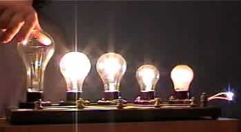
Let one of the lamps turn off in this example and the current in the line will decrease to 5 A. In this case, the voltage drop in the line will decrease: ΔUl = IRl = 5 x 0.8 = 4 V.
On the switched-on lamp, the voltage will rise, which will cause a noticeable increase in its brightness. The example shows that turning on or off an individual receiver causes a change in the voltage of other receivers due to a change in the voltage drop in the line. These phenomena explain the voltage fluctuations that are often observed in electrical networks.
The effect of line resistance on the network voltage value is characterized by the relative voltage loss. The ratio of the voltage drop in the line to the normal voltage, expressed as a percentage relative voltage loss (denoted by ΔU%), is called:
ΔU% = (ΔUl /U)x100%
According to existing standards, the conductors of the line must be designed so that the voltage loss does not exceed 5%, and under lighting load does not exceed 2 — 3%.
Loss of energy
Some of the electrical energy generated by the generator passes into heat and is wasted in lime, causing heating by conduction. As a result, the energy received by the receiver is always less than the energy given by the generator. Likewise, the power consumed in the receiver is always less than the power developed by the generator.
The power loss in the line can be calculated by knowing the current strength and resistance of the line: Plosses = Az2Rl
To characterize the efficiency of power transmission, define line efficiency, which is understood as the ratio of the power received by the receiver to the power developed by the generator.
Since the power developed by the generator is greater than the power of the receiver by the amount of power loss in the line, the efficiency (denoted by the Greek letter η — this) is calculated as: η = Puseful / (Puseful + Plosses)
where, Ppolzn is the power consumed in the receiver, Ploss is the power loss in the lines.
From the example discussed earlier with current strength Az = 10 Power loss in the line (Rl = 0.8 ohms):
Loss = Az2Rl = 102NS0, 8 = 80 W.
Useful power P useful = Ulamps x I = 212x 10 = 2120 W.
Efficiency η = 2120 / (2120 + 80) = 0.96 (or 96%), i.e. the receivers receive only 96% of the power generated by the generator.
Heating with wire
Heating of wires and cables due to the heat generated by electric current is a harmful phenomenon. With prolonged operation at elevated temperatures, the insulation of wires and cables ages, becomes brittle and collapses. Destruction of the insulation is unacceptable, as this creates the possibility of contact of the bare parts of the wires with each other and the so-called short circuit.
Touching exposed wires can cause electric shock. Finally, excessive heating of the wire can ignite its insulation and cause a fire.
To ensure that the heating does not exceed the permissible value, you must choose the correct cross-section of the wire. The greater the current, the greater the cross-section a wire must have, because as the cross-section increases, the resistance decreases and, accordingly, the amount of heat generated decreases.
The selection of the cross-section of the heating wires is carried out according to the tables that show how much current can pass through the wire without causing unacceptable overheating.va. Sometimes they indicate the permissible current density, that is, the amount of current per square millimeter of the cross section of the wire.
Current density Ј is equal to the strength of the current (in amperes) divided by the cross-section of the conductor (in square millimeters): Ј = I / S а / mm2
Knowing the permissible current density Јadditionally, you can find the necessary conductor section: S = I /Јadop
For internal wiring, the permissible current density is on average 6A/mm2.
An example. It is necessary to determine the cross-section of the wire, if it is known that the current passing through it should be equal to I = 15A, and the permissible current density Јadop — 6Аmm2.
Decision. Required wire cross-section S = I /Јadop = 15/6 = 2.5 mm2