Compile a control program for a programmable controller
 Programmable controllers are designed for cyclically programmed control of metal-cutting machines and various technological equipment, equipped with sensors and actuators that work on the two-position "on-off" principle. In the article, the process of compiling a control program is considered on the example of a controller of the MKP-1 model.
Depending on the version, this controller allows you to control 16, 32 or 48 devices. The number of input circuits for connecting sensors corresponds to the number of outputs. Each input and output has its own address.
The controller provides control of drives, receiving information from sensors about the state of the equipment, generating delays, organizing conditional and unconditional transitions according to the control program, and also performs other functions.
The design of the control device is reduced to two stages: 1 — drawing up a diagram for connecting sensors and actuators to the controller, 2 — drawing up a control program according to the algorithmic scheme.
Connecting sensors
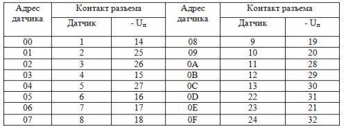
DIP buttons and sensors are connected to the input connectors of the controller according to Table 1. Each input has its own address.
To power the input circuits, a power supply with output voltage Un = 20 … 30 V is required. Triggering the sensor corresponds to the closing of the input circuit (binary level 1), the open state of the circuit is equivalent to binary level 0.
An example of connecting the sensor contact to the controller input is shown in fig. 1
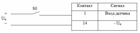
Fig. 1. Connection diagram of the sensor contact
Table 1. Controller input circuits
Connection of executive devices
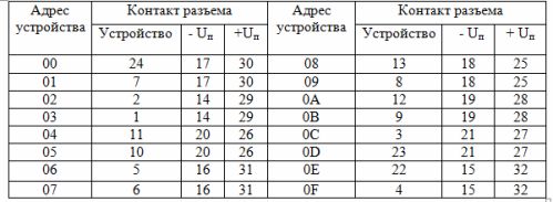
Actuators (relay coils, input circuits of non-contact devices) are connected to the output connectors of the controller in accordance with table 2.
Table 2. Output circuits of the controller
An example of connecting the relay coils to the controller outputs is shown in fig. 2.
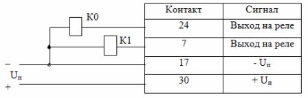
Fig. 2. Wiring diagram of relay coils
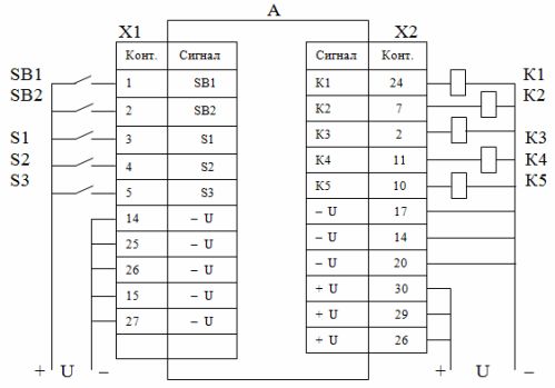
An example of a complete scheme for connecting external devices to the controller
Digital System Controller
The controller works with numbers expressed in hexadecimal notation. The basis of the system is the decimal number 16, the alphabet consists of ten digits (0 ... 9) and six Latin letters (A, B, C, D, E, F). The letters correspond to decimal numbers 10, 11, 12, 13, 14, 15.
Learn more about the hexadecimal number system: Number systems
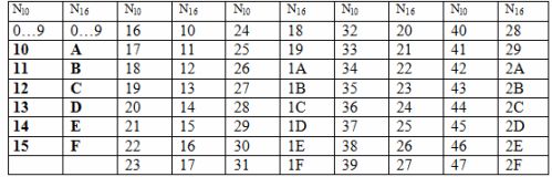
During programming, all numeric values are specified in hexadecimal. Table 3 shows a range of numbers in hexadecimal N16 and their decimal equivalents Nl0.
Table 3. Numbers in hexadecimal notation
A set of controller commands
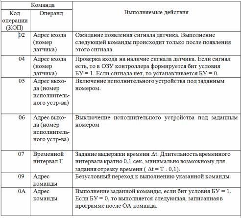
The programmable controller is equipped with a control system designed to solve software control problems. Table 4 shows a small part of the controller commands.
The command consists of two parts: the code of the operation to be performed (CPC) and the operand, which indicates the address of the object on which the operation is performed. In this case, both the sensors and the actuators and commands of the program itself act as such an object. When specifying time intervals, the operand is the duration of those intervals.
Table 4. Controller command set
Diagrams of algorithms
The order of operation of each device can be described using graphic symbols that form an algorithm diagram. Four types of symbols called vertices can be used when constructing a diagram (Fig. 3).
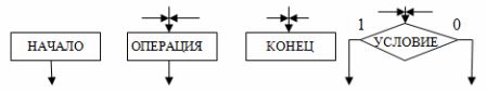
Rice. 3. Vertices of the algorithmic scheme
The «Start» vertex corresponds to the initial state of the control device before the impact on it by the controls, for example the «Start» button.
The "End" vertex corresponds to the end of the control process, for example, after pressing the "Stop" button.
The operating point corresponds to the execution of a certain elementary operation of the devices that make up the control device, for example, switching on or off a relay. The operation performed is recorded on the chart inside the top icon.
A conditional vertex defines the condition for moving from one operating vertex to another. The condition is set by the sensor, control button or other device. The state of the sensor or button and the outputs of the vertices, respectively, are indicated by the numbers 1 or 0.
For example: motion switch «on» — 1; "Off" — 0.
Compiling an algorithm diagram is reduced to connecting vertices in accordance with the required order of operation of the automated device. A fragment of the diagram of the algorithm is shown in fig. 4. In the diagram, the symbol X1 stands for the switch, Δt is the time interval.
Compilation of a control program
Each command in the program is written under its own serial number, which is its address. The program is compiled according to the scheme of the algorithm and must contain a set of commands that perform all the operations specified in the scheme.
Before developing the program, it is necessary to draw up a connection diagram of sensors and drives. Depending on where these devices are connected, they get their own number, which is their address in the program.
The creation of the program should start from the top of the «Start» diagram and then sequentially program the operations to the top «End».
If an operation is performed after a button, limit switch, or other sensor is actuated, then command 02 is set and the number of that sensor is written as the operand. In this case, the controller will execute the command to turn on or off the executive devices only after receiving a trigger signal from this sensor.
The devices are turned on or off with commands 05 or 06, respectively. The number of the turned on device is written to the operand
Time intervals are set using command 07. The coefficient is written in the operand, which when multiplied by 0.1 sec. gives the necessary delay time.
For example, when setting t = 2.6 sec.the operand contains the number 1A (26 in decimal notation). The maximum time delay set by a single 07 command is 25.5 sec (07 FF command). If it is necessary to obtain a delay greater than 25.5 seconds, then several 07 commands must be successively included in the control program, together providing the required time interval.
To implement conditional jumps in the program (in the algorithm diagram, a conditional vertex with both «1» and «0» operations), you must first set the check command to this vertex 04.
If the sensor corresponding to this vertex is in state «1», then the condition bit BU = 1 will be generated. If the sensor is in state «0», then BU = 0 will be generated.
The OA command is then issued, which, if BU = 1 was set in the previous command, will switch the controller to execute the command specified in the operand of that command.
With BU = 0, the controller will execute the command after the OA command.
When compiling a program, it is recommended to first write a sequence of commands for the controller to execute when BU = 0, without specifying the operand in the OA command. After all the commands executed by the controller according to the «0» condition are written, the command , fulfilled according to condition «1», is entered into the program. The address of this command is specified in the operand of the OA command.
NOTE: For the condition bit, the initial state is BU = 1, which is set after the controller is turned on and after the conditional jump commands are executed.
An example of writing a program for a fragment of the algorithm diagram in Fig. 4 is shown in Table 5.
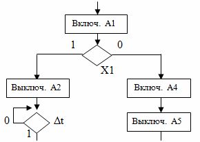
Rice. 4. Fragment of the diagram of the algorithm
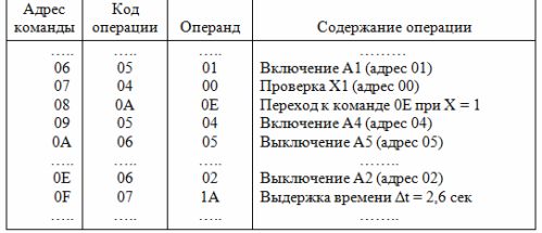
Table 5. Fragment of the management program