Engine start and brake circuits
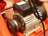 Currently, the most common three-phase squirrel-cage rotor induction motors. Starting and stopping such motors when switched on at full mains voltage is carried out remotely using magnetic starters.
The most commonly used circuit is with one starter and control buttons «Start» and «Stop». To ensure rotation of the motor shaft in both directions, a circuit with two starters (or with a reversing starter) and three buttons is used. This scheme allows you to change the direction of rotation of the motor shaft "on the fly" without stopping it first.
Engine starting diagrams
The electric motor M is powered by a three-phase alternating voltage network. The QF three-phase circuit breaker is designed to disconnect the circuit in the event of a short circuit. The single-phase SF circuit breaker protects the control circuits.
The main element of the magnetic starter is the contactor KM (power relay for switching high currents). Its power contacts switch three phases suitable for the electric motor. Button SB1 («Start») is for starting the engine, and button SB2 («Stop») is for stopping.Thermal bimetallic relays KK1 and KK2 disconnect the circuit when the current consumed by the electric motor is exceeded.
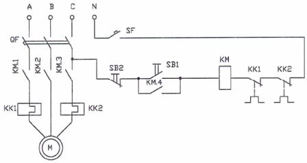
Rice. 1. Scheme for starting a three-phase asynchronous motor using a magnetic starter
When the SB1 button is pressed, the contactor KM is activated and the contacts KM.1, KM.2, KM.3 connect the electric motor to the network, and with the contact KM.4 it blocks the button (self-locking).
To stop the electric motor, it is enough to press the button SB2, while the contactor KM releases and turns off the electric motor.
An important property of the magnetic starter is that in the event of an accidental loss of voltage in the network, the motor is turned off, but the restoration of the voltage in the network does not lead to a spontaneous start of the motor, because when the voltage is turned off, the contactor KM is released and for to turn it back on, press the SB1 button.
In the event of a malfunction of the installation, for example, when the rotor of the motor jams and stops, the current consumed by the motor increases several times, which leads to the operation of the thermal relays, the opening of contacts KK1, KK2 and the shutdown of the installation. Returning the KK contacts to the closed state is done manually after the fault has been removed.
A reversible magnetic starter allows not only starting and stopping an electric motor, but also changing the direction of rotation of the rotor. For this purpose, the starter circuit (Fig. 2) contains two sets of contactors and start buttons.
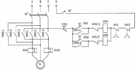
Rice. 2. Scheme for starting the engine using a reversible magnetic starter
The KM1 contactor and the SB1 self-locking button are designed to turn on the engine in the «forward» mode, and the KM2 contactor and the SB2 button include the «reverse» mode.To change the direction of rotation of the rotor of a three-phase motor, it is enough to change any two of the three phases of the supply voltage, which is provided by the main contacts of the contactors.
Button SB3 is designed to stop the motor, contacts KM 1.5 and KM2.5 are blocked, and thermal relays KK1 and KK2 provide protection against overcurrent.
Starting the motor at full line voltage is accompanied by high inrush currents, which may be unacceptable for a limited supply network.
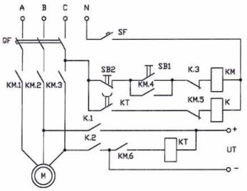
The circuit for starting an electric motor with starting current limitation (Fig. 3) contains resistors R1, R2, R3 connected in series with the windings of the motor. These resistors limit the current at the time of starting when the contactor KM is activated after pressing the button SB1. Simultaneously with KM, when the contact KM.5 is closed, the time relay KT is activated.
The delay provided by the timing relay should be sufficient to accelerate the motor. At the end of the holding time, the contact KT closes, the relay K is activated and through its contacts K.1, K.2, K.3 maneuvers the starting resistors. The starting process is complete and the engine is at full voltage.
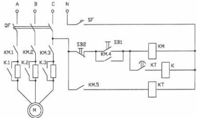
Rice. 3. Scheme of starting the motor with starting current limitation
Next, we will look at two of the most popular braking schemes for three-phase squirrel-cage induction motors: a dynamic braking scheme and an inverse braking scheme.
Engine brake chains
After removing the voltage from the motor, its rotor continues to rotate for some time due to inertia. In a number of devices, for example in lifting and conveying mechanisms, a forced stop is required to reduce the amount of overhang.Dynamic braking consists in the fact that after the removal of the alternating voltage, a direct current passes through the windings of the electric motor.
The dynamic braking circuit is shown in Fig. 4.
Rice. 4. Dynamic engine braking diagram
In the circuit, in addition to the main contactor KM, there is a relay K, which turns on the stop mode. Since the relay and contactor cannot be turned on at the same time, a blocking scheme is used (contacts KM.5 and K.3).
When the SB1 button is pressed, the contactor KM is activated, energizing the motor (contacts KM.1 KM.2, KM.3), blocking the button (KM.4) and blocking the relay K (KM.5). Closing KM.6 activates the KT time relay and closes the KT contact without time delay. So the engine starts.
To stop the engine, press the SB2 button. Contactor KM is released, contacts KM.1 — KM.3 open, turning off the motor, contact KM.5 closes, which activates relay K. Contacts K.1 and K.2 close, supplying direct current to the coils. A rapid stop occurs.
When the contact KM.6 opens, the time relay KT is released, the delay begins. The dwell time must be sufficient to bring the engine to a complete stop. At the end of the delay, contact KT opens, relay K releases and removes DC voltage from the motor windings.
The most effective way to stop is to reverse the motor, when immediately after the power is turned off, a voltage is applied to the electric motor, which causes the appearance of a counter torque. The opposite braking circuit is shown in fig. 5.
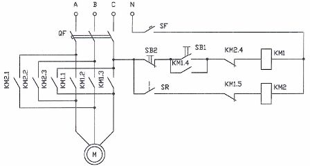
Rice. 5. Engine brake circuit by opposition
Motor speed is monitored by a speed relay with SR contact.If the speed is higher than a certain value, the SR contact closes. When the motor stops, contact SR opens. In addition to the direct contactor KM1, the circuit contains a reversing contactor KM2.
When the engine is started, the contactor KM1 is activated and with the contact KM 1.5 breaks the circuit of the coil KM2. When a certain speed is reached, the SR contact closes, preparing the circuit to engage reverse.
When the motor stops, contactor KM1 releases and closes contact KM1.5. As a result, contactor KM2 activates and supplies reverse voltage to the braking motor. A decrease in rotor speed causes SR to open, contactor KM2 releases, braking stops.