Charging and discharging the capacitor
Capacitor charge
To charge the capacitor, you need to connect it to the DC circuit. In fig. 1 shows the capacitor charging circuit. Capacitor C is connected to the terminals of the generator. The key can be used to close or open the circuit. Let's take a detailed look at the process of charging a capacitor.
The generator has internal resistance. When the switch is closed, the capacitor will charge to a voltage between the plates equal to e. etc. v. generator: Uc = E. In this case, the plate connected to the positive terminal of the generator receives a positive charge (+q), and the second plate receives an equal negative charge (-q). The size of the charge q is directly proportional to the capacity of the capacitor C and the voltage on its plates: q = CUc
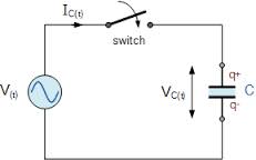
Pe. 1… Capacitor charging circuit
In order to charge the capacitor plates, it is necessary for one of them to gain and the other to lose a certain amount of electrons.The transfer of electrons from one plate to another is carried out along the external circuit by the electromotive force of the generator, and the process of moving charges along the circuit is nothing more than an electric current, called a charging capacitive current A charge
The charging current in value usually flows in thousandths of a second until the voltage across the capacitor reaches a value equal to e. etc. v. generator. The graph of the voltage rise on the plates of the capacitor during its charging is shown in fig. 2, a, from which it can be seen that the voltage Uc increases smoothly, first rapidly, and then more and more slowly, until it becomes equal to e. etc. v. generator E. After that, the voltage across the capacitor remains unchanged.
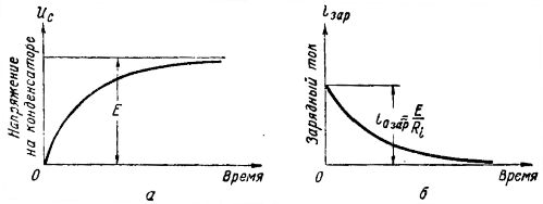
Rice. 2. Graphs of voltage and current when charging a capacitor
As the capacitor charges, a charging current flows through the circuit. The charge current graph is shown in Fig. 2, b. At the initial moment, the charging current has the largest value, since the voltage in the capacitor is still zero, and according to Ohm's law iotax = E /Ri, since all e., etc. c generator is applied to resistance Ri.
As the capacitor charges, that is, increases the voltage across it, it decreases for the charging current. When there is already a voltage across the capacitor, the voltage drop across the resistance will be equal to the difference between e. etc. v. generator and capacitor voltage, i.e. equal to E — U s. Therefore itax = (E-Us) / Ri
From here it can be seen that as Uc increases, icharge and at Uc = E the charging current becomes zero.
Read more about Ohm's Law here: Ohm's law for a section of a circuit
The duration of the capacitor charging process depends on two quantities:
1) from the internal resistance of the generator Ri,
2) from the capacitance of the capacitor C.
In fig. 2 shows the graphs of the elegant currents for a capacitor with a capacity of 10 microfarads: curve 1 corresponds to the charging process from a generator with e. etc. with E = 100 V and with an internal resistance Ri= 10 Ohm, curve 2 corresponds to the charging process from a generator with the same e. pr. with, but with a lower internal resistance: Ri = 5 ohms.
From a comparison of these curves, it can be seen that with a lower internal resistance of the generator, the strength of the elegant current at the initial moment is greater and therefore the charging process is faster.
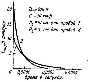
Rice. 2. Graphs of charging currents at different resistances
In fig. 3 compares the graphs of charging currents when charging from the same generator with e. etc. with E = 100 V and internal resistance Ri= 10 ohms of two capacitors with different capacities: 10 microfarads (curve 1) and 20 microfarads (curve 2).
Initial charging current iotax = E /Ri = 100/10 = 10 Both capacitors are the same, since a capacitor with a larger capacity stores more electricity, then its charging current should take longer, and the charging process is more - long.
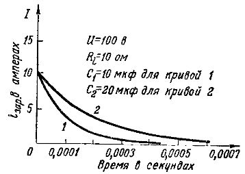
Rice. 3. Tables of charging currents with different capacities
Capacitor discharge
Disconnect the charged capacitor from the generator and attach a resistance to its plates.
There is a voltage on the plates of the capacitor Us, therefore, in a closed circuit, a current called the discharge capacitive current ires will flow.
Current flows from the positive plate of the capacitor through the resistance to the negative plate. This corresponds to the transition of excess electrons from the negative plate to the positive, where they are absent.The process of row frames takes place until the potentials of the two plates are equal, i.e. the potential difference between them becomes zero: Uc = 0.
In fig. 4a shows the graph of the decrease of the voltage in the capacitor during discharge from the value Uco = 100 V to zero, and the voltage first decreases rapidly, and then more slowly.
In fig. 4, b shows the graph of the changes in the discharge current. The strength of the discharge current depends on the value of the resistance R and according to Ohm's law ires = Uc/R
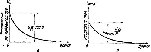
Rice. 4. Graphs of voltage and currents during capacitor discharge
At the initial moment, when the voltage on the plates of the capacitor is the greatest, the discharge current is also the greatest, and with a decrease in Uc during the discharge, the discharge current also decreases. At Uc = 0, the discharge current stops.
The duration of the disposal depends on:
1) from the capacitance of the capacitor C
2) on the value of the resistance R to which the capacitor discharges.
The greater the resistance R, the slower the discharge will occur. This is due to the fact that with a large resistance, the strength of the discharge current is small and the amount of charge on the plates of the capacitor decreases slowly.
This can be shown in the graphs of the discharge current of the same capacitor, with a capacity of 10 μF and charged to a voltage of 100 V, at two different values of resistance (Fig. 5): curve 1 — at R =40 ohms, ioresr = UcО/ R = 100/40 = 2.5 A and curve 2 — at 20 Ohm ioresr = 100/20 = 5 A.
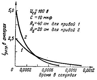
Rice. 5. Graphs of the discharge currents at different resistances
The discharge is also slower when the capacitance of the capacitor is large.This is because with more capacitance on the capacitor plates, there is more electricity (more charge) and it will take a longer period of time for the charge to drain. This is clearly shown by the graphs of the discharge currents for two capacitors of the same capacity, charged to the same voltage of 100 V and discharged to a resistance R= 40 ohms (Fig. 6: curve 1 — for a capacitor with a capacity of 10 microfarads and curve 2 — for capacitor with a capacity of 20 microfarads).
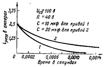
Rice. 6. Graphs of the discharge currents at different powers
From the considered processes, it can be concluded that in a circuit with a capacitor, the current flows only at the moments of charging and discharging, when the voltage on the plates changes.
This is explained by the fact that when the voltage changes, the amount of charge on the plates changes, and this requires the movement of charges along the circuit, that is, an electric current must pass through the circuit. A charged capacitor does not pass direct current because the dielectric between its plates opens the circuit.
Capacitor energy
During the charging process, the capacitor stores energy by receiving it from the generator. When a capacitor is discharged, all the energy of the electric field is converted into heat energy, that is, it goes to heat the resistance through which the capacitor is discharged. The greater the capacitance of the capacitor and the voltage across its plates, the greater the energy of the capacitor's electric field. The amount of energy possessed by a capacitor of capacity C charged to a voltage U is equal to: W = Wc = CU2/2
An example. Capacitor C = 10 μF charged to voltage Uc = 500 V.Determine the energy that will be released in the force of heat at the resistance through which the capacitor is discharged.
Answer. During discharge, all the energy stored by the capacitor will be converted into heat. Therefore W = Wc = CU2/2 = (10 x 10-6 x 500) / 2 = 1.25 J.