Thyristor contact management
 If the power thyristor elements are designed to simply turn on, turn off the motor or stop it, then it is rational to use relatively simple and reliable control circuits. They are based on the use of anode voltage to generate the firing pulses. The opening angle in these schemes is not adjustable or adjustable in a small range. Let's consider the principle of such control using the example of a single-phase thyristor element (Fig. 1, a).
If thyristor control electrodes connect to each other through some resistor RControl, then under the action of the anode voltage, a control current arises. For example, with the positive polarity of terminal A, the control current iynp flows through the control node of the thyristor (cathode — control electrode) in the opposite direction, since the diode properties of the control p-n-junctions are negligible.
In addition, the current iynp flows through contact K, the control resistor Rynp p-n- junction of the thyristor T2, the load Z "to the negative terminal B. Thus, for the thyristor T2, whose anode voltage is positive, the control current is also positive.As a result, thyristor T2 will open as soon as the control current reaches the required value.
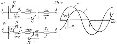
Rice. 1. Thyristor switch: a — circuit without diodes, 6 — diagram of currents and voltages, c — circuit with diodes
The thyristor T2 in the open state bypasses the control circuit and the current in it stops, i.e. an automatic cut-off of the current is obtained. There are short-term control pulses (Fig. 1, b) following with alternating polarity during each half-cycle immediately after the current passes through zero.
The opening angle depends on the resistance Rypp and Zn. As Rcontrol increases, the control current later reaches the required value and the angle α increases. This control method can be used to regulate the voltage and current in the load. However, due to the large dispersion of the thyristor parameters, the angles α are obtained different, which leads to asymmetry of the thyristor element and the appearance of non-sinusoidal currents in the load.
If the thyristor element works only in switching mode, without adjusting the voltage on the load, then it is called a tristor contactor... In fig. 1, c shows a diagram of a single-phase AC contactor, where the control node is shunted by a diode that stabilizes the angle α.
In fig. 2, a, b shows examples of simplified schemes that enable the control of thyristors in DC circuits in the most economical way.
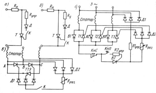
Rice. 2. Circuits for contact control of thyristors
To open the thyristor, the mains voltage is applied to the gate electrode through resistor R control, diode D and closed contact K.When the instantaneous voltage increases to the value of Uotc, the thyristor opens, the voltage drop ΔU across it decreases to almost zero. The control current through the diode is terminated, a pulse is obtained. Note that in order to open the thyristor in some cases (Fig. 2, a), the contacts K must be closed, and in others (Fig. 2, b) - open.
In fig. 2, c shows a tristor scheme for controlling an induction motor. A rectified voltage is supplied to the control electrodes of the thyristors through diodes D1 and D2 from the tips of the thyristor triangular element ABC. The peaks are equipotential points during the conduction periods of every two thyristors. Therefore, the control voltage exists during these narrow periods of time when one of the three thyristors is on.
When the contacts K are closed, a three-phase system of unipolar pulses acting on the thyristors is created. If the switch is open, then the signals are stopped and the thyristors are turned off when the current passes through zero. The engine turns off. Groups of diodes D1 and D2 allow you to create a rectified current section where you can install an Rpeg rheostat to adjust the opening angle and a K switch.
Thyristor contactors
In fig. 2, d shows the control scheme of the valve-thyristor elements forming a star in the stator winding of the electric motor.
When the KNP button is pressed, the auxiliary thyristor VT opens and supplies pulses taken from the zero point of the stator winding to the control electrodes through the regulating rheostat Rreg and diodes D2. Resistor R1cont is required to maintain thyristor VT in the open state when the KNP button is open.
The fact is that the opening pulses taken from the zero point of the stator winding are narrow, and when the button KNP opens, the auxiliary resistor VT can be turned off. To prevent this, it is necessary to create a path to maintain the anode current.
Resistor R1control with three-phase rectifier creates a latching circuit similar to the blocking contacts that surround the knV button magnetic starter circuit… Resistor R2control limits the control current. Resistor Rpez, as in the previous scheme, is a regulating resistor that provides a change in the opening angle in a small range (α =30 + 50°).