Electronic amplifiers in industrial electronics
 These are devices designed to amplify the voltage, current and power of an electrical signal.
The simplest amplifier is a transistor circuit. The use of amplifiers is due to the fact that usually electrical signals (voltages and currents) entering electronic devices are of small amplitude and it is necessary to increase them to the necessary value sufficient for further use (conversion, transmission, power supply to the load ).
Figure 1 shows the devices required to operate the amplifier.
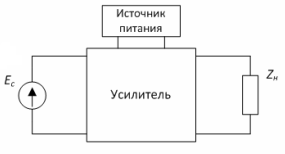

Figure 1 — Amplifier environment
The power released when the amplifier is loaded is the converted power of its power supply and the input signal only drives it. The amplifiers are powered by direct current sources.
Usually, the amplifier consists of several amplification stages (Fig. 2). The first stages of amplification, designed mainly to amplify the signal voltage, are called preamplifiers. Their circuits are determined by the type of input signal source.
The stage that serves to amplify the power of the signal is called the terminal or output.Their scheme is determined by the type of load. Also, the amplifier may include intermediate stages designed to obtain the necessary amplification and (or) to form the necessary characteristics of the amplified signal.
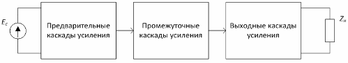
Figure 2 — Amplifier structure
Amplifier Classification:
1) depending on the amplified parameter, voltage, current, power amplifiers
2) by the nature of the amplified signals:
-
amplifiers of harmonic (continuous) signals;
-
pulse signal amplifiers (digital amplifiers).
3) in the range of amplified frequencies:
-
DC amplifiers;
-
AC amplifiers
-
low frequency, high, ultra high etc.
4) by the nature of the frequency response:
-
resonant (amplify signals in a narrow frequency band);
-
bandpass (amplifies a certain frequency band);
-
wideband (amplifies the entire frequency range).
5) by type of reinforcing elements:
-
of electric vacuum lamps;
-
on semiconductor devices;
-
on integrated circuits.
When selecting an amplifier, exit the amplifier parameters:
-
output power measured in watts. Output power varies widely depending on the purpose of the amplifier, for example in sound amplifiers — from milliwatts in headphones to tens and hundreds of watts in audio systems.
-
Frequency range, measured in hertz. For example, the same audio amplifier should usually provide gain in the frequency range 20–20,000 Hz, and a television signal amplifier (image + sound) — 20 Hz — 10 MHz and higher.
-
Nonlinear distortion, measured in percent%. It characterizes the shape distortion of the amplified signal. Generally, the lower a given parameter, the better.
-
Efficiency (efficiency ratio) is measured in percent%.Shows how much power from the power supply is being used to dissipate power into the load. The fact is that part of the power of the source is wasted, to a greater extent these are heat losses — the flow of current always causes heating of the material. This parameter is especially important for self-powered devices (from accumulators and batteries).
Figure 3 shows a typical bipolar transistor preamp circuit. The input signal comes from a voltage source Uin. The blocking capacitors Cp1 and Cp2 pass the variable ie. amplified signal and do not pass direct current, which makes it possible to create independent operating modes for direct current in series-connected amplifier stages.
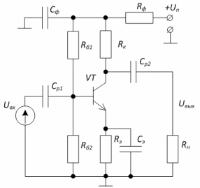
Figure 3 — Diagram of the amplifier stage of a bipolar transistor
Resistors Rb1 and Rb2 are the main divider providing the starting current to the base of the transistor Ib0, the resistor Rk provides the starting current to the collector Ik0. These currents are called laminar currents. In the absence of an input signal, they are constant. Figure 4 shows the timing diagrams of the amplifier. A time plot is a change in a parameter over time.
Resistor Re provides negative current feedback (NF). Feedback (OC) is the transfer of a portion of the output signal to the input circuit of the amplifier. If the input signal and the feedback signal are opposite in phase, the feedback is said to be negative. OOS reduces gain, but at the same time reduces harmonic distortion and increases amplifier stability. It is used in almost all amplifiers.
Resistor Rf and capacitor Cf are filter elements.The capacitor Cf forms a low resistance circuit for the variable component of the current consumed by the amplifier from the source Up. Filtering elements are necessary if several amplifier sources are fed from the source.
When an input signal Uin is applied, the current Ib ~ appears in the input circuit, and in the output Ik ~. The voltage drop created by the current Ik ~ through the load Rn will be the amplified output signal.
From the temporary diagrams of voltages and currents (Fig. 3) it can be seen that the variable components of the voltages at the input Ub ~ and the output Uc ~ = Uout of the cascade are antiphase, i.e. the gain stage of the OE transistor changes (inverts) the phase of the input signal in the opposite direction.
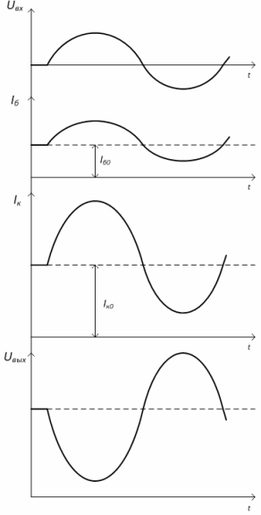
Figure 4 — Timing diagrams of currents and voltages in the amplifier stage of a bipolar transistor
An operational amplifier (OU) is a DC/AC amplifier with high gain and deep negative feedback.
It allows the implementation of a large number of electronic devices, but is traditionally called an amplifier.
We can say that operational amplifiers are the backbone of all analog electronics. The wide use of operational amplifiers is associated with their flexibility (the ability to build various electronic devices on their basis, both analog and pulsed), a wide frequency range (amplification of DC and AC signals), independence of the main parameters from external destabilizing factors (temperature change, supply voltage, etc.). Integrated amplifiers (IOUs) are mainly used.
The presence of the word "operational" in the name is explained by the possibility that these amplifiers can perform a number of mathematical operations - addition, subtraction, differentiation, integration, etc.
Figure 5 shows the UGO IEE.The amplifier has two inputs — forward and reverse and one output. When the input signal is applied to a non-inverting (direct) input, the output signal has the same polarity (phase) — Figure 5, a.
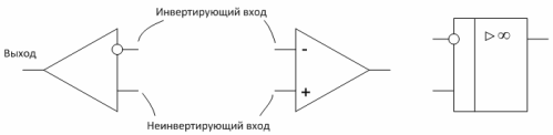
Figure 5 — Conventional graphic designations of operational amplifiers
When using the inverting input, the phase of the output signal will be shifted by 180 ° relative to the phase of the input signal (polarity reversed) — Figure 6, b. Reverse inputs and outputs are circled.
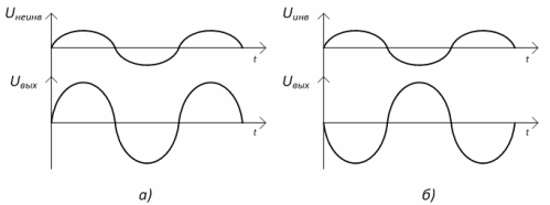
Figure 6 — Time diagrams of the op-amp: a) — non-inverting, b) — inverting
When a voltage is applied to the wallpaper, the output voltage is proportional to the difference between the input voltages. These. the inverting input signal is accepted with a «-« sign. Uout = K (Uneinv — Uinv), where K is the gain.
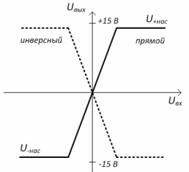
Figure 7 — Amplitude characteristic of the op-amp
The op-amp is powered by a bipolar source, usually +15V and -15V. A unipolar power supply is also allowed. The rest of the IOU conclusions are indicated as they are used.
The operation of the op-amp is explained by the amplitude characteristic - Figure 8. On the characteristic, a linear section can be distinguished, in which the output voltage increases proportionally with an increase in the input voltage, and two sections of saturation U + sat and U- sat. At a certain value of the input voltage Uin.max, the amplifier goes into saturation mode, in which the output voltage assumes a maximum value (at a value of Up = 15 V, approximately Uns = 13 V) and remains unchanged with a further increase in the input signal. The saturation mode is used in pulse devices based on operational amplifiers.
Power amplifiers are used in the final stages of amplification and are designed to create the required power in the load.
Their main feature is operation at high input signal levels and high output currents, which necessitates the use of powerful amplifiers.
Amplifiers can operate in A, AB, B, C and D modes.
In mode A, the output current of the amplifier device (transistor or electronic tube) is open for the entire period of the amplified signal (ie, constantly) and the output current flows through it. Class A power amplifiers introduce minimal distortion into the amplified signal, but have very low efficiency.
In mode B, the output current is divided into two parts, one amplifier amplifies the positive half-wave of the signal, the second negative. As a result, higher efficiency than in mode A, but also large non-linear distortions occurring at the moment of switching transistors.
The AB mode repeats the B mode, but at the moment of transition from one half-wave to the other, both transistors are open, which makes it possible to reduce distortions while maintaining high efficiency. AB mode is the most common for analog amplifiers.
Mode C is used in cases where there is no distortion of the waveform during amplification, because the output current of the amplifier flows for less than half a period, which, of course, leads to large distortions.
D mode uses converting input signals into pulses, amplifying those pulses, and then converting them back.In this case, the output transistors work in key mode (the transistor is fully closed or fully open), which brings the efficiency of the amplifier closer to 100% (in AV mode, the efficiency does not exceed 50%). Amplifiers operating in D mode are called digital amplifiers.
In a push-pull circuit, amplification (modes B and AB) occurs in two clock cycles. During the first half-cycle, the input signal is amplified by one transistor, and the other is closed during this half-cycle or part of it. In the second half-cycle, the signal is amplified by the second transistor while the first is turned off.
The sliding circuit of the transistor amplifier is shown in Figure 8. The transistor stage VT3 provides a push to the output transistors VT1 and VT2. Resistors R1 and R2 set the constant mode of operation of the transistors.
With the arrival of a negative half-wave Uin, the collector current VT3 increases, which leads to an increase in the voltage at the bases of transistors VT1 and VT2. In this case, VT2 closes and through VT1 the collector current passes through the circuit: + Up, transition K-E VT1, C2 (during charging), Rn, case.
When a positive half-wave arrives, Uin VT3 closes, which leads to a decrease in the voltage at the bases of transistors VT1 and VT2 — VT1 closes, and through VT2 the collector current flows through the circuit: + C2, transition EK VT2 , case, Rn, -C2 . T
This ensures that the current of both half-waves of the input voltage flows through the load.
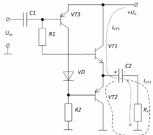
Figure 8 — Schematic of a power amplifier
In mode D, the amplifiers operate with pulse width modulation (PWM)… The input signal modulates rectangular pulsesby changing their duration.In this case, the signal is converted into rectangular pulses of the same amplitude, the duration of which is proportional to the value of the signal at any moment in time.
The pulse train is fed to the transistor(s) for amplification. Because the amplified signal is pulsed, the transistor operates in key mode. Operation in key mode is associated with minimal losses, since the transistor is either closed or fully open (has minimal resistance). After amplification, the low-frequency component (amplified original signal) is extracted from the signal using a low-pass filter (LPF) and fed to the load.
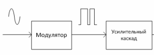
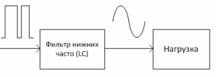
Figure 9 — Block diagram of a class D amplifier
Class D amplifiers are used in laptop audio systems, mobile communications, motor control devices, and more.
Modern amplifiers are characterized by the widespread use of integrated circuits.