Current, voltage, power: basic characteristics of electricity
 Electricity has long been used by man to satisfy his needs, but it is invisible, not perceived by the senses, therefore it is difficult to understand. To simplify the explanation of electrical processes, they are often compared to the hydraulic characteristics of a moving fluid.
For example, she comes to our apartment by wire Electrical energy from remote generators and tap water from a pressure pump. However, the switch turns off the lights and the closed water faucet prevents water from running out of the faucet. To do the job, you need to turn on the switch and open the faucet.
A directed flow of free electrons through the wires will rush to the filament of the bulb (an electric current will flow) which will emit light. The water coming out of the faucet will drain into the sink.
This analogy also makes it possible to understand the quantitative characteristics, to relate the strength of the current to the speed of movement of the liquid and to estimate other parameters.
The mains voltage is compared to the energy potential of the liquid source. For example, an increase in hydraulic pressure from a pump in a pipe will create a high velocity of fluid movement, and an increase in voltage (or the difference between the potentials of the phase - the input wire and the working zero - the output) will increase the incandescence of the bulb, the strength of its radiation .
The resistance of the electrical circuit is compared to the braking force of the hydraulic flow. Flow rate is affected by:
-
liquid viscosity;
-
clogging and change in the cross-section of the channels. (In the case of a water faucet, the position of the control valve.)
The value of electrical resistance is affected by several factors:
-
the structure of the substance that determines the presence of free electrons in a conductor and affects resistance;
-
cross-sectional area and length of the current conductor;
-
temperature.
Electric power is also compared to the energy potential of the flow in hydraulics and is estimated from the work done per unit time. The power of an electrical appliance is expressed by the current drawn and the applied voltage (for AC and DC circuits).
All these characteristics of electricity were studied by famous scientists who gave definitions of current, voltage, power, resistance and described by mathematical methods the mutual relations between them.
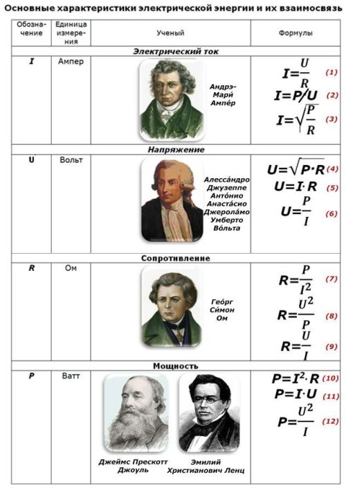
The following table shows general relationships for AC and DC circuits that can be used to analyze the performance of specific circuits.
Let's look at some examples of their use.
Example #1. How to calculate resistance and power
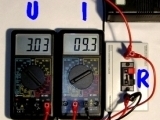
Suppose you want to select a current limiter to power the lighting circuit. We know the supply voltage of the on-board network «U», equal to 24 volts and the current consumption «I» of 0.5 amps, which must not be exceeded. According to the expression (9) of Ohm's law, we calculate the resistance «R». R = 24 / 0.5 = 48 ohms.
At first glance, the value of the resistor is determined. However, this is not enough. For the reliable operation of sema, it is necessary to calculate the power according to the current consumption.
According to the operation of the Joule-Lenz law, the active power «P» is directly proportional to the current «I» passing through the wire and the applied voltage «U». This relationship is described by formula (11) in the table below.
We calculate: P = 24×0.5 = 12 W.
We get the same value if we use formulas (10) or (12).
Calculating the power of the resistor by its current consumption shows that in the selected circuit it is necessary to use a resistance of 48 Ohm and 12 W. A resistor with a lower power will not withstand the applied loads, it will heat up and burn out with current of time.
This example shows the dependence of how load current and network voltage affect the user's power.
Example #2. How to calculate the current
For a group of sockets intended for powering household electrical appliances in the kitchen, it is necessary to select a protective circuit breaker. The power of the devices according to the passport data is 2.0, 1.5 and 0.6 kW.
Answer. The apartment uses a 220-volt single-phase AC network. The total power of all devices connected to work at the same time will be 2.0 + 1.5 + 0.6 = 4.1 kW = 4100 W.
Using the formula (2), we determine the total current of the group of consumers: 4100/220 = 18.64 A.
The closest rated circuit breaker has a tripping rate of 20 amps. We choose it. A machine with a lower value than 16 A will permanently shut down from overload.
Differences in the parameters of electrical circuits in alternating current
Single-phase networks
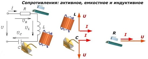
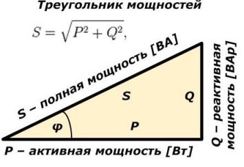
When analyzing the parameters of electrical appliances, it is necessary to take into account the peculiarities of their operation in alternating current circuits, when, due to the influence of the industrial frequency, capacitive loads appear in the capacitors (they shift the current vector by 90 degrees ahead of the voltage vector), and in the windings of the coil — inductive (the current is 90 degrees behind the voltage). In electrical engineering they are called reactive loads... Together they create reactive power losses «Q» that do no useful work.
With active loads, there is no phase shift between current and voltage.
In this way, a reactive component is added to the active value of the power of an electrical appliance in alternating current circuits, due to which the total power increases, which is usually called full and is indicated by the index «S».
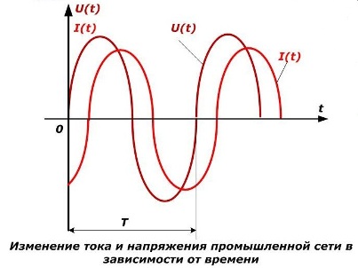
Alternating sinusoidal current in a single-phase network
Electric current and frequency voltage vary with time in a sinusoidal manner. Accordingly, there is a change in power. Determining their parameters at different points in time does not make much sense. Therefore, the total (integrating) values are selected for a certain period of time, as a rule, the oscillation period T.
Knowing the differences between the parameters of alternating and direct current circuits allows you to correctly calculate the power through current and voltage in each specific case.
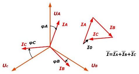
Three-phase networks
Basically, they consist of three identical single-phase circuits, offset relative to each other on the complex plane by 120 degrees. They differ slightly in the loads in each phase, shifting the current from the voltage by an angle phi. Due to this unevenness, a current I0 is created in the neutral conductor.
 Alternating sinusoidal current in a three-phase network
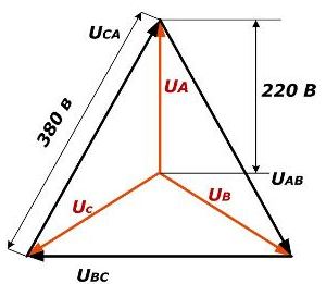
The voltage in this system consists of phase voltages (220 V) and line voltages (380 V).
The power of a three-phase current device connected to the circuit is the sum of the components in each phase. It is measured using special devices: wattmeters (active component) and varmeters (reactive). It is possible to calculate the total power consumption of a three-phase current device based on the wattmeter and varmeter measurements using the triangle formula.
There is also an indirect measurement method based on the use of a voltmeter and ammeter with subsequent calculations of the obtained values.
You can also calculate the total current consumption, knowing the magnitude of the apparent power S. To do this, it is enough to divide it by the value of the line voltage.