The principle of operation of the RCD
 The abbreviation RCD was created from the expression "Residual current device", which defines the purpose of the device, which consists in removing voltage from the circuit connected to it in the event of accidental insulation failures and the formation of leakage currents through them.
Operating principle
The operation of the RCD uses the principle of comparing the currents entering the controlled part of the circuit and the currents leaving it based on a differential transformer that converts the primary values of each vector into secondary values strictly proportional in angle and direction for geometric gathering.
The method of comparison can be represented by a simple balance sheet or balance sheet.

When the balance is maintained, then everything works normally, and when it is disturbed, the quality state of the entire system changes.
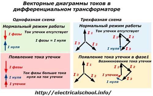
In a single-phase circuit, the phase current vector approaching the measuring element and the zero leaving it are compared. During normal operation with reliable integral insulation, they are equal, balancing each other.When a fault occurs in the circuit and a leakage current appears, then the balance between the considered vectors is disturbed by its value, which is measured by one of the windings of the transformer and transmitted to the logic block.
The comparison of currents in a three-phase circuit is carried out according to the same principle, only currents from the three phases pass through a differential transformer and an imbalance is created based on their comparison. In normal operation, the currents of the three phases are balanced in geometric summation, and in case of insulation failures in each phase, a leakage current occurs in it. Its value is determined by summing the vectors in the transformer.
Structure diagram
The simplified operation of a residual current device can be represented by blocks in a block diagram.
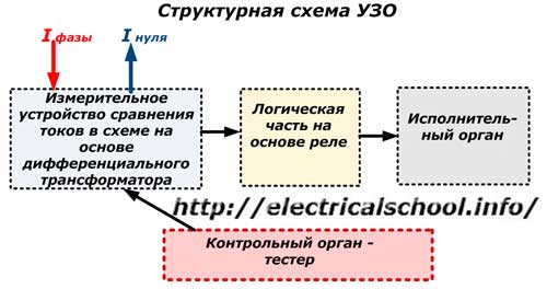
The imbalance of the currents from the measuring device is directed to the logic part, which works on the relay principle:
1. electromechanical;
2. or electronic.
It is important to understand the difference between the two. Electronic systems are now booming and becoming increasingly popular for many reasons. They have wide functionality, great capabilities, but require electrical power to operate the logic and executive element, which is provided by a special block that is connected to the main circuit. If the electricity goes out for various reasons, then such an RCD, as a rule, will not work. The exception is rare electronic models equipped with this function.
Electromechanical relays use the mechanical energy of a charged spring, which basically looks like a regular mousetrap. For the relay to operate, a minimum mechanical force is sufficient on the actuated actuator.
When the mouse touches the lure of the prepared mouse trap, the leakage current, which has occurred in the case of an imbalance in the differential transformer, causes the drive to actuate and cut the voltage from the circuit. For this, the relay has built-in power contacts in each phase and a contact for preparing the tester.
Each type of relay has certain advantages and disadvantages. Electromechanical designs have been working reliably for many decades and have proven themselves well. They do not require an external power supply and electronic models are completely dependent on it.
It is now generally accepted that the most effective measure of protection against electric shock in electrical installations up to 1000 V is a residual current device (RCD) for the leakage current.
Without opposing the importance of this protection measure, most experts have been arguing for many years about the values of the main parameters of the RCD — installation current, response time and reliability. This is explained by the fact that the parameters of the RCD are narrow related to its price and working conditions.
In fact, the lower the setting current and the shorter the response time, the higher the reliability of the RCD, the more expensive its price.
In addition, the smaller the setting current and the shorter the operating time of the RCD, the stricter the requirements for the isolation of the protected area, since even a slight deterioration in operating conditions can lead to frequent, and in some cases and long, false shutdowns of the electrical installation, which makes normal work impossible.
On the other hand, the higher the RCD setting current and the longer the response time, the worse its protective properties.
RCD design
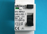
The layout of a single-phase RCD is shown in the photo below.
In it, the voltage is applied to the input terminals, and a controlled circuit is connected to the output terminals.
The three-phase residual current device is made in the same way, but in it the currents of all phases are observed.
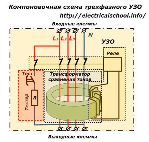
The figure shown shows a four-wire RCD, although a three-wire design is commercially available.
How to check the RCD
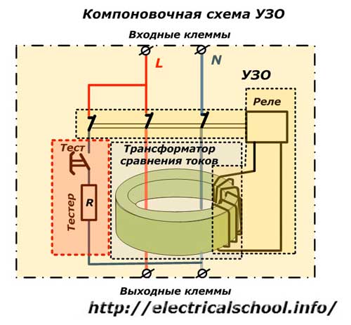
Functional verification is built into every design pattern. For this, the «Tester» block is used, which is an open contact-spring button for self-adjustment and a current-limiting resistor R. Its value is chosen to create a minimum sufficient current that artificially simulates leakage.
When the «Test» button is pressed, the RCD associated with the operation must be switched off. If this does not happen, it should be rejected, checked for damage and repaired or replaced with serviceability. Testing the residual current device (RCD) on a monthly basis increases the reliability of its operation.
By the way, the serviceability of electromechanical and individual electronic structures is easy to check in a store before purchase. For this purpose, it is enough, when the relay is turned on, to briefly supply a current in the phase or neutral circuit from the battery with any polarity of the connection according to options 1 and 2.
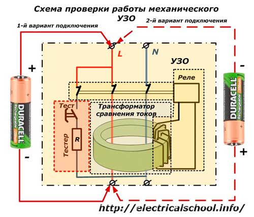
A working RCD with an electromechanical relay will work and in the vast majority of cases electronic products cannot be checked. They need power for the logic to work.
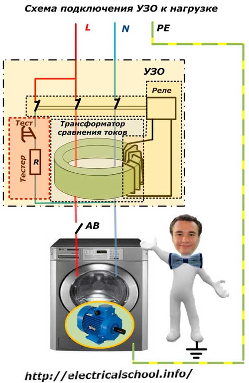
How to connect an RCD to a load
Residual current devices are intended for use in supply circuits using the TN-S or TN-C-S system with the connection of the protective neutral PE bus in the wiring, to which the housings of all electrical devices are connected.
In this situation, if the insulation is broken, the potential arising on the body immediately passes through the PE conductor to the ground and the comparator calculates the fault.
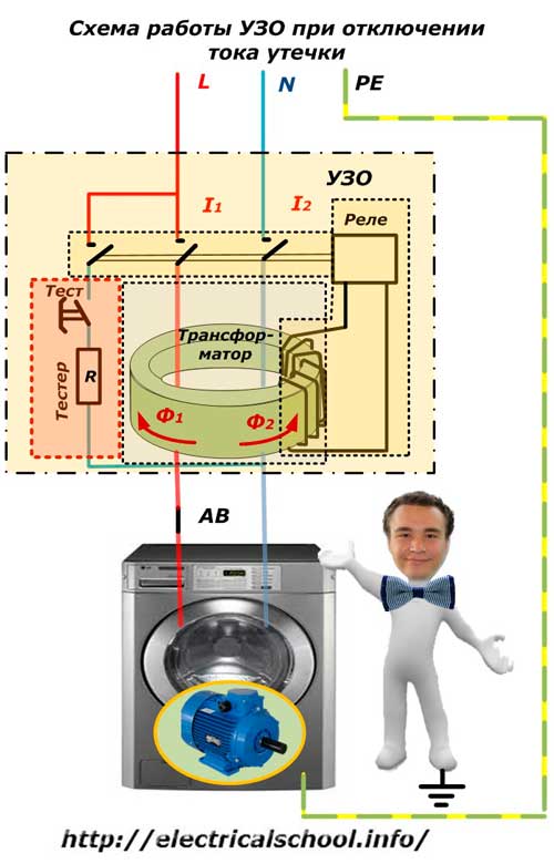
In normal power mode, the RCD does not disconnect the load, so all electrical appliances work optimally. The current of each phase induces its own magnetic flux F in the magnetic circuit of the transformer. Since they are equal in magnitude but opposite in direction, they cancel each other out. There is no common magnetic flux and cannot induce an EMF in the relay coil.
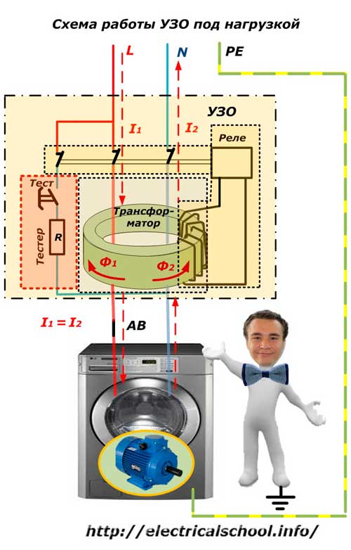
In case of leakage, the dangerous potential flows to earth through the PE bus. In the coil of the relay, an EMF is induced by the resulting imbalance of the magnetic fluxes (currents in phase and neutral).
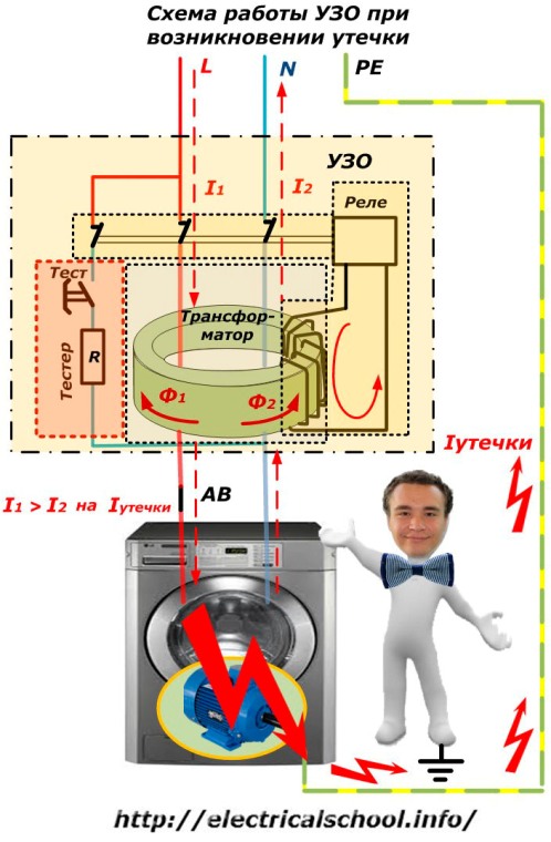
The residual current device immediately calculates the fault in this way and in a fraction of a second disconnects the circuit with power contacts.
Characteristics of an RCD with an electromechanical relay
Using the mechanical energy of the charged spring can in some cases be more advantageous than using a special block to power the logic circuit. Consider this with an example when the zero of the supply network is interrupted and the phase occurs.
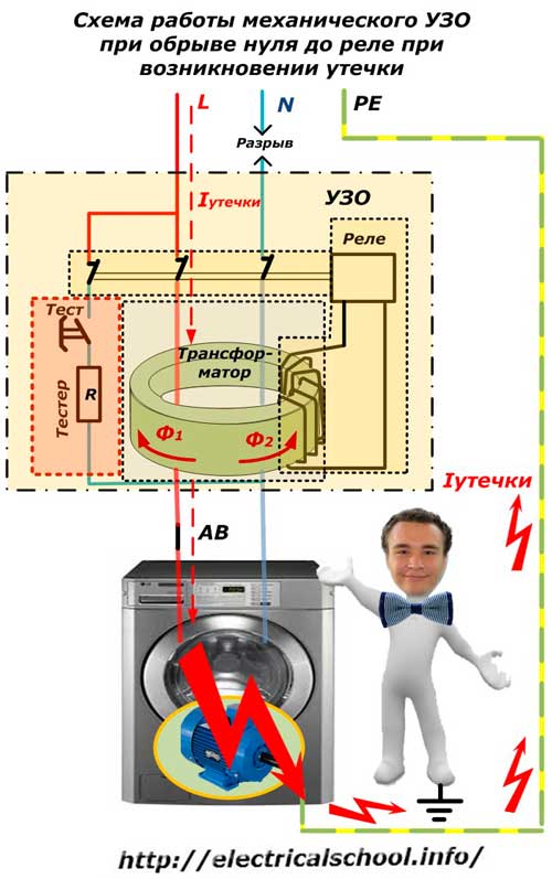
In such a situation, the static electronic relays will not receive power and therefore will not be able to operate. At the same time, in this situation, a three-phase system has a phase imbalance and an increase in voltage.
If an insulation failure occurs at a weakened location, then the potential will appear on the housing and leave through the PE conductor.
In RCDs with a relay for electromechanical protection, they work normally from the energy of the charged spring.
How an RCD works in a two-wire circuit
The indisputable advantages of protection against leakage currents in electrical equipment made according to the TN-S system through the use of RCDs have led to their popularity and the desire of individual apartment owners to install RCDs in a two-wire that is not equipped with a PE conductor.
In this situation, the housing of the electrical appliance is isolated from the ground, it does not communicate with it. If an insulation failure occurs, the phase potential appears on the enclosure rather than draining from it. A person who is in contact with earth and accidentally touches the device is affected by the leakage current in the same way as in a situation without an RCD.
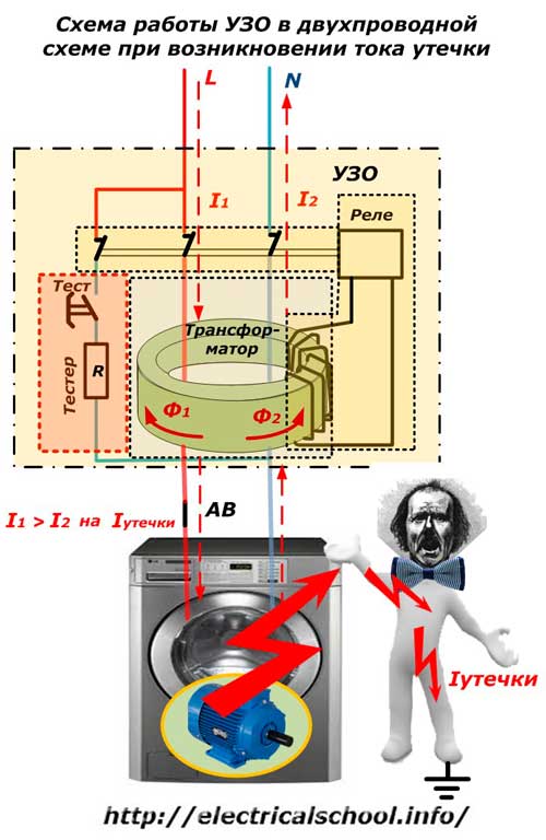
However, in a circuit without a residual current device, the current can pass through the body for a long time. When an RCD is installed, it will sense a fault and cut the voltage during setup within fractions of a second, reducing damaging effect of current and the degree of electrical injury.
In this way, the protection facilitates the rescue of a person when powering in buildings equipped with a TN-C scheme.
Many home craftsmen try to install an RCD on their own in old houses that are awaiting reconstruction in order to switch to the TN-C-S system. At the same time, in the best case, they perform a self-made ground loop or simply connect the boxes of electrical appliances to the water network, heating batteries and iron parts of the foundation.
Such connections can create critical situations when malfunctions occur and cause serious damage. The work of creating the earth loop must be done efficiently and controlled by electrical measurements. Therefore, they are carried out by trained specialists.
Types of installation
Most RCDs are made in a stationary design for common Din-bus mounting in the switchboard. However, on sale you can find portable structures that are connected to an ordinary electrical outlet, and the protected device is additionally powered by them. They cost a little more.