Hall sensor applications
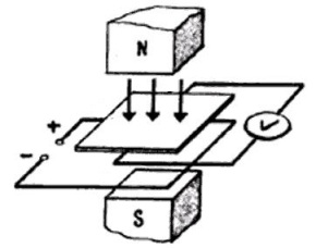
 In 1879, while working on his doctoral dissertation at Johns Hopkins University, the American physicist Edwin Herbert Hall conducted an experiment with a gold plate. He passed a current through the plate by placing the plate itself on the glass and, in addition, the plate was subjected to the action of a magnetic field directed perpendicular to its plane and, accordingly, perpendicular to the current.
In fairness, it should be noted that at this time Hall was engaged in solving the question of whether the resistance of the coil through which the current flows depends on the presence next to it permanent magnet, and within this work scientists have conducted thousands of experiments. As a result of the gold plate experiment, a certain potential difference was found at the side edges of the plate.
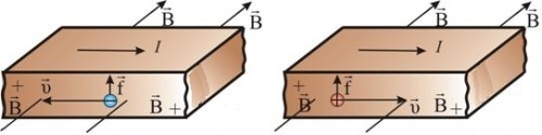
This voltage is called the Hall voltage... The process can be roughly described as follows: the Lorentz force causes a negative charge to accumulate near one edge of the plate, and a positive one near the opposite edge.The ratio of the resulting Hall voltage to the value of the longitudinal current is a characteristic of the material from which a certain Hall element is made, and this value is called the «Hall resistance».
The Hall effect serves as a fairly accurate method for determining the type of charge carriers (hole or electron) in a semiconductor or metal.
Based on the Hall Effect, they now produce Hall Sensors, devices for measuring the strength of a magnetic field and determining the strength of a current in a wire. Unlike current transformers, Hall sensors make it possible to measure direct current as well. Thus, the application areas of the Hall effect sensor are generally quite extensive.
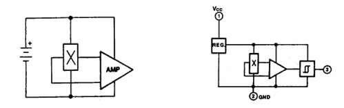
Since the Hall voltage is small, it is only logical that the Hall voltage terminals are connected operational amplifier… To connect to digital nodes, the circuit is supplemented with a Schmitt trigger and a threshold device is obtained, which is triggered at a given level of magnetic field strength. Such circuits are called Hall switches.
Often a Hall sensor is used in conjunction with a permanent magnet and is triggered when the permanent magnet approaches the sensor within a certain predetermined distance.
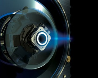
Hall sensors are quite common in brushless or valve electric motors (servo motors), where the sensors are installed directly on the motor stator and act as a rotor position sensor (RPR) that provides feedback on the rotor position, similar to a collector in collector DC motor.
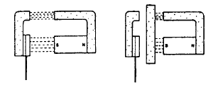
By fixing a permanent magnet on the shaft, we get a simple revolution counter, and sometimes the shielding effect of the ferromagnetic part itself on the magnetic flux of permanent magnet… The magnetic flux from which Hall sensors are typically triggered is 100-200 Gauss.
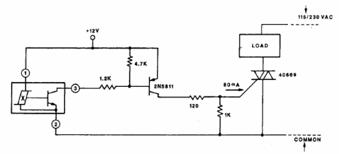
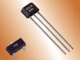
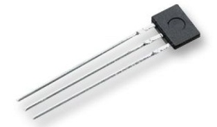
Manufactured by the modern electronics industry, three-wire Hall sensors have an open-collector n-p-n transistor in their package. Often, the current through the transistor of such a sensor should not exceed 20 mA, therefore, in order to connect a powerful load, it is necessary to install a current amplifier.
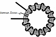
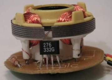
The magnetic field of a current-carrying conductor is usually not strong enough to trigger a Hall sensor, since the sensitivity of such sensors is 1-5 mV / G, and therefore, to measure weak currents, a current-carrying conductor is wound on a toroidal core with gap and a Hall sensor is already installed in the gap ... So with a gap of 1.5 mm, the magnetic induction will now be 6 Gs / A.
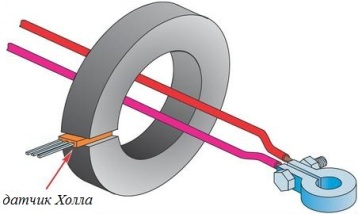
For measuring currents above 25 A, the current conductor passes directly through the toroidal core. The core material can be alcifer or ferrite if measured high frequency current.
Some ion-jet engines work on the basis of the Hall effect and work very efficiently.
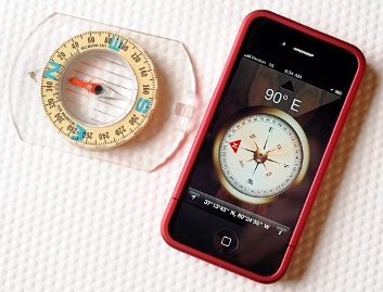
The Hall effect is the basis for electronic compasses in modern smartphones.