Single-phase rectifiers - schemes and principle of operation
 A rectifier is a device designed to convert an input AC voltage into a DC voltage. The main module of the rectifier is a set of vein saws that directly converts AC to DC voltage.
If it is necessary to match the parameters of the network with the parameters of the load, the rectifier set is connected to the network through a matching transformer. According to the number of phases of the supply network, rectifiers are single-phase and three phases… See more details here — Classification of semiconductor rectifiers… In this article we will consider the operation of single-phase rectifiers.
Single-phase half-wave rectifier
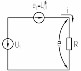
The simplest rectifier circuit is a single-phase half-wave rectifier (Fig. 1).
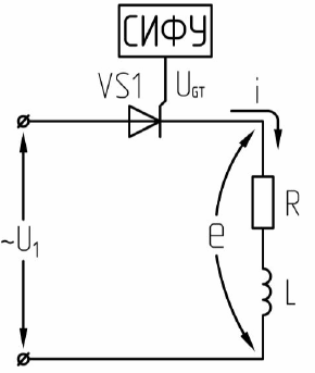
Rice. 1. Schematic of a single-phase controlled half-wave rectifier
Schematics of operation of the R-load rectifier are shown in Figure 2.
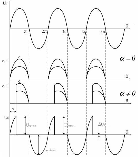
Rice. 2. Schemes of operation of the rectifier for R-load
To open the thyristor, two conditions must be met:
1) the potential of the anode must be higher than the potential of the cathode;
2) an opening pulse must be applied to the control electrode.
For this circuit, the simultaneous fulfillment of these conditions is possible only during positive half-cycles of the supply voltage. A pulse phase control system (SIFU) should form opening pulses only in positive NSoluneriods of the supply voltage.
When applying for thyristor VS1 of the opening pulse at the moment of time θ = α thyristor VS1 opens and the supply voltage U is applied to the load1 during the remainder of the positive half cycle (forward voltage drop across the valve ΔUv insignificant compared to the voltage U1 (ΔUv = 1 — 2 V) ). Since the load R — active, then the current in the load repeats the shape of the voltage.
At the end of the positive half-cycle, the load current i and the valve VS1 will decrease to zero (θ = nπ), and the voltage U1 will change its sign. Therefore, a reverse voltage is applied to thyristor VS1, under the action of which it closes and restores its control properties.
Such switching of valves under the influence of the voltage of the power source, which periodically changes its polarity, is called natural.
It can be seen from the diagrams that a change in one wire leads to a change in part of the positive half-cycle during which the supply voltage is applied to the load, and therefore this leads to a regulation of the power consumption. Injection α characterizes the delay in the moment of opening of the thyristor compared to the moment of its natural opening and is called the opening (control) angle of the valve.
The emf and rectifier current are successive segments of positive half-sine waves, constant in direction but not constant in magnitude, i.e. the rectified EMF and current have a periodic pulsating character. And any periodic function can be expanded in Fourier series:
e (t) = E + en(T),
where E is the constant component of the corrected EMF, en(T) — variable component equal to the sum of all harmonic components.
Thus, we can assume that a constant EMF distorted by the variable component en (t) is applied to the load. The permanent component of the EMF E is the main characteristic of the rectified EMF.
The process of regulating the load voltage by changing it is called phase control... This scheme has several disadvantages:
1) high content of higher harmonics in the corrected EMF;
2) large ripples of EMF and current;
3) intermittent circuit operation;
4) use of low circuit voltage (kche =0.45).
The interrupting current mode of operation of the rectifier is such a mode in which the current in the load circuit of the rectifier is interrupted, i.e. becomes zero.
Single-phase single-half-wave rectifier when operating on an active-inductive load
The timing diagrams of half-wave rectifier operation for RL-load are shown in Fig. 3.
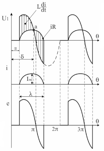
Rice. 3. Diagrams of half-wave rectifier operation for RL-load
To analyze the processes taking place in the scheme, let us allocate three time intervals.
1. α <θ <δ… The equivalent circuit corresponding to this interval is shown in fig. 4.
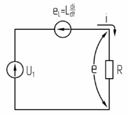 Re. 4. Equivalent circuit for α <θ <δ
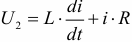
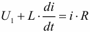
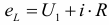
According to the equivalent scheme:
During this time interval eL (self-induction EMF) is biased back to the grid voltage U1 and prevents a sharp increase in current. The energy from the network is converted to heat at R and is accumulated in the electromagnetic field with inductance L.
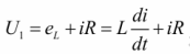
2. α <θ < π. The equivalent circuit corresponding to this interval is shown in Fig. 5.
Fig. 5… Equivalent circuit for α <θ < π
At this interval, the EMF of self-induction eL changed its sign (at this time θ = δ).
At θ δ dL changes its sign and tends to maintain the current in the circuit. It is directed according to U1. In this interval, the energy from the network and accumulated in the field of inductance L is converted into heat in R.
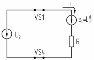
3. π θ α + λ. The equivalent circuit corresponding to this interval is shown in Fig. 6.
Rice. 6 Equivalent circuit
At some point in time θ = π the line voltage U1 changes its polarity, but the thyristor VS1 remains in the conducting state because egL exceeds U1 and the forward voltage is maintained across the thyristor. The current under the action of dL will flow through the load in the same direction, while the energy stored in the field of inductance L will not be completely consumed.
In this interval, part of the energy accumulated in the inductive field is converted into heat in the resistance R, and part is transmitted to the network. The process of transferring energy from a DC circuit to an AC circuit is called inversion… This is evidenced by the different signs of e and i.
The duration of the current flow in the section with negative polarity U1 depends on the ratio between the quantities L and R (XL=ωL). The greater the ratio — ωL/ R, the greater the duration of the current flow λ.
If there is an inductance in the load circuit L, then the current shape becomes smoother and the current flows even in areas of negative polarity U1... In this case, the thyristor VS1 does not close during the transition of the voltage U1 through 0 and at the moment the current drops to zero. If ωL/ R→oo, then in α = 0 λ → 2π.
The principle of operation of a single-phase bridge rectifier in continuous mode when operating active and active-inductive loads
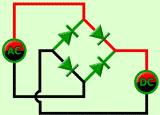
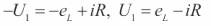
The power circuit of a single-phase bridge rectifier is shown in Fig. 7, and the time diagrams of its work on the active load are shown in fig. eight.
The valve bridge (Fig. 7) contains two groups of valves — cathode (odd valves) and anode (even valves). In the bridge circuit, current is carried simultaneously by two valves — one from the cathode group and one from the anode group.
As can be seen from fig. 7, the gates are turned on so that during the positive half-cycles of the voltage U2, the current flows through the gates VS1 and VS4, and during the negative half-cycles through the gates VS2 and VS3. We make the assumption that the valves and the transformer are ideal, i.e. Ltp = Rtp = 0, ΔUB = 0.
Rice. 7. Scheme of a single-phase bridge rectifier
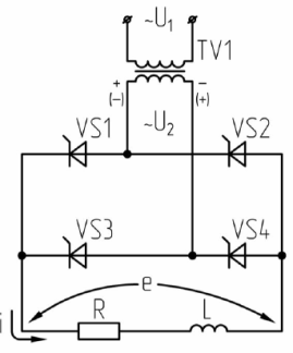
Rice. 8. Schemes of operation of a single-phase bridge-controlled rectifier on a resistive load
In this circuit, at any instant of time, a pair of thyristors VS1 and VS4 conducts current in positive half-cycles U2 and VS2 and VS3 in negative. When all thyristors are closed, half the supply voltage is applied to each of them.
At θ =α open VS1 and VS4 and the load starts to flow through the open VS1 and VS4. The previous VS2 and VS3 operate at full mains voltage in the reverse direction.When v = l-, U2 changes sign and since the load is active, the current becomes zero and reverse voltage is applied to VS1 and VS4 and they close.
At θ =π +α thyristors VS2 and VS3 open and the load current continues to flow in the same direction. The current in this circuit at L = 0 has an intermittent character, and only at α= 0 will the current be marginally continuous.
Limit continuous mode is a mode in which the current at some moments of time decreases to zero, but is not interrupted.
Upr.max = Uobr.max = √2U2(with transformer),
Upr.max = Uobr.max = √2U1(without transformer).
Circuit operation for an active-inductive load
The R-L load is typical of windings of electrical apparatus and field windings of electrical machines or when an inductive filter is installed at the output of the rectifier. The influence of inductance affects the shape of the load current curve as well as the average and effective values of the current through the valves and the transformer. The higher the inductance of the load circuit, the lower the alternating current component.
To simplify the calculations, it is assumed that the load current is perfectly smoothed (L→oo). This is legal when ωNSL> 5R, where ωNS — the circular frequency of the rectifier output ripple. If this condition is met, the calculation error is insignificant and can be ignored.
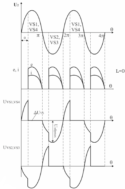
The timing diagrams of the operation of a single-phase bridge rectifier for an active-inductive load are shown in Fig. nine.
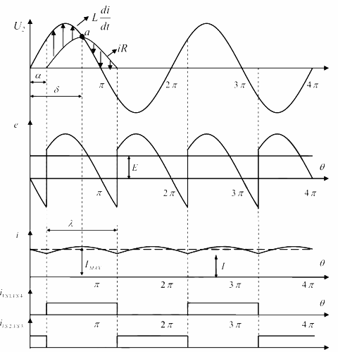
Rice. 9. Schemes of operation of a single-phase bridge rectifier when operating on an RL load
To examine the processes taking place in the scheme, we will separate three areas of work.
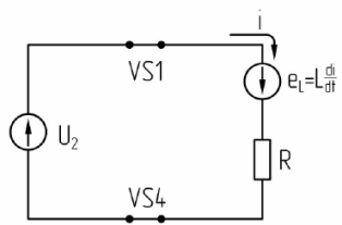
1. a. The equivalent circuit corresponding to this interval is shown in Fig.ten.
 Rice. 10. Equivalent circuit of a rectifier
In the considered interval, the energy from the network is converted into heat in the resistance R and a part accumulates in the electromagnetic field of the inductance.
2. α <θ < π. The equivalent circuit corresponding to this interval is shown in Fig. eleven.
 Rice. 11. Equivalent circuit of the rectifier for α <θ < π
At a moment in time θ = δ the EMF of self-induction eL = 0 because the current reaches its maximum value.
In this interval, the energy accumulated in the inductance and consumed by the network is converted into heat in the resistance R.
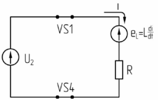
3. π θ α + λ. The equivalent circuit corresponding to this interval is shown in Fig. 12.
 Rice. 12. Equivalent circuit of the rectifier at π θ α + λ
In this interval, part of the energy accumulated in the inductive field is converted into heat in resistance R, and part is returned to the network.
The action of the EMF of self-induction in the 3rd section leads to the appearance of sections with negative polarity in the curve of the corrected EMF, and the different signs of e and i indicate that in this interval there is a return of electrical energy to the network.
If at time θ = π + α the energy stored in the inductance L is not completely consumed, then the current i will be continuous. When at a certain time θ = π + α opening pulses are served to thyristors VS2 and VS3, to which a forward voltage is supplied from the network side, they open and through them a reverse voltage is applied to the operating VS1 and VS4 from the network side, as a result of which they close, this type of switching is called natural.