A practical application of Faraday's law of electromagnetic induction
The word "induction" in Russian means the processes of excitation, direction, creation of something. In electrical engineering, this term has been used for more than two centuries.
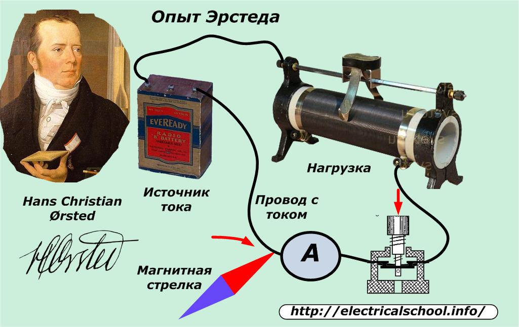
After reading the publications of 1821 describing the experiments of the Danish scientist Oersted on the deflections of a magnetic needle near a conductor carrying an electric current, Michael Faraday set himself the task: convert magnetism into electricity.
After 10 years of research, he formulated the basic law of electromagnetic induction, explaining that an electromotive force is induced in any closed loop. Its value is determined by the rate of change of the magnetic flux penetrating the considered loop, but taken with a minus sign.
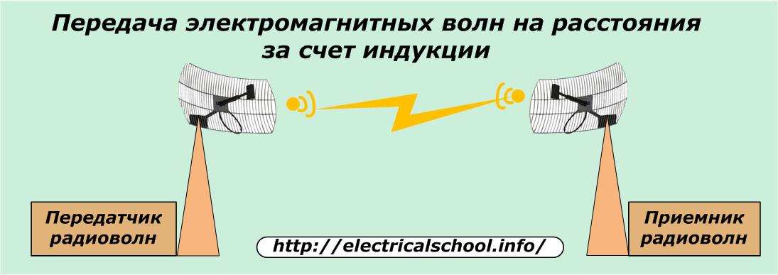
Transmission of electromagnetic waves at a distance
The first guess that came to the mind of the scientist was not crowned with practical success.
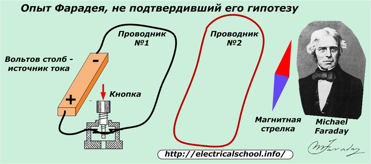
He placed two closed wires side by side.Near one I installed a magnetic needle as an indicator of the passing current, and in the other wire I gave an impulse from a powerful galvanic source of that time: a volt pole.
The researcher hypothesized that with a current pulse in the first circuit, the changing magnetic field in it would induce a current in the second wire, which would deflect the magnetic needle. But the result turned out to be negative - the indicator does not work. Rather, he lacked sensitivity.
The brain of the scientist foresees the creation and transmission of electromagnetic waves at a distance, which are now used in radio broadcasting, television, wireless control, Wi-Fi technologies and similar devices. He was simply frustrated by the imperfect element base of the measuring devices of that time.
Electricity production
After a bad experiment, Michael Faraday changed the conditions of the experiment.
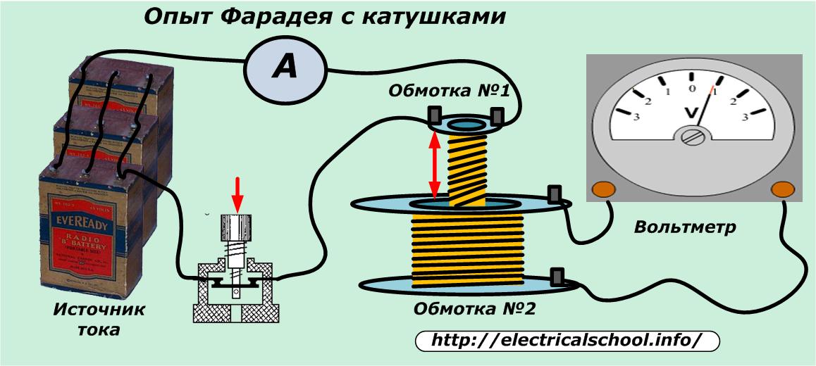
For the experiment, Faraday used two closed-loop coils. In the first circuit he fed an electric current from a source, and in the second he observed the appearance of an EMF. The current passing through the turns of coil #1 creates a magnetic flux around the coil, penetrates coil #2 and forms an electromotive force in it.
During Faraday's experiment:
- turn on a pulse to supply voltage to the circuit with stationary coils;
- when the current was applied, it introduced the upper coil into the lower coil;
- fixed coil No. 1 permanently and introduced coil No. 2 into it;
- changed the speed of movement of the coils relative to each other.
In all these cases he observed the manifestation of EMF induction in the second coil. And with only direct current passing through winding No. 1 and stationary coils, there was no electromotive force.
The scientist determined that the EMF induced in the second coil depends on the rate at which the magnetic flux changes. It is proportional to its size.
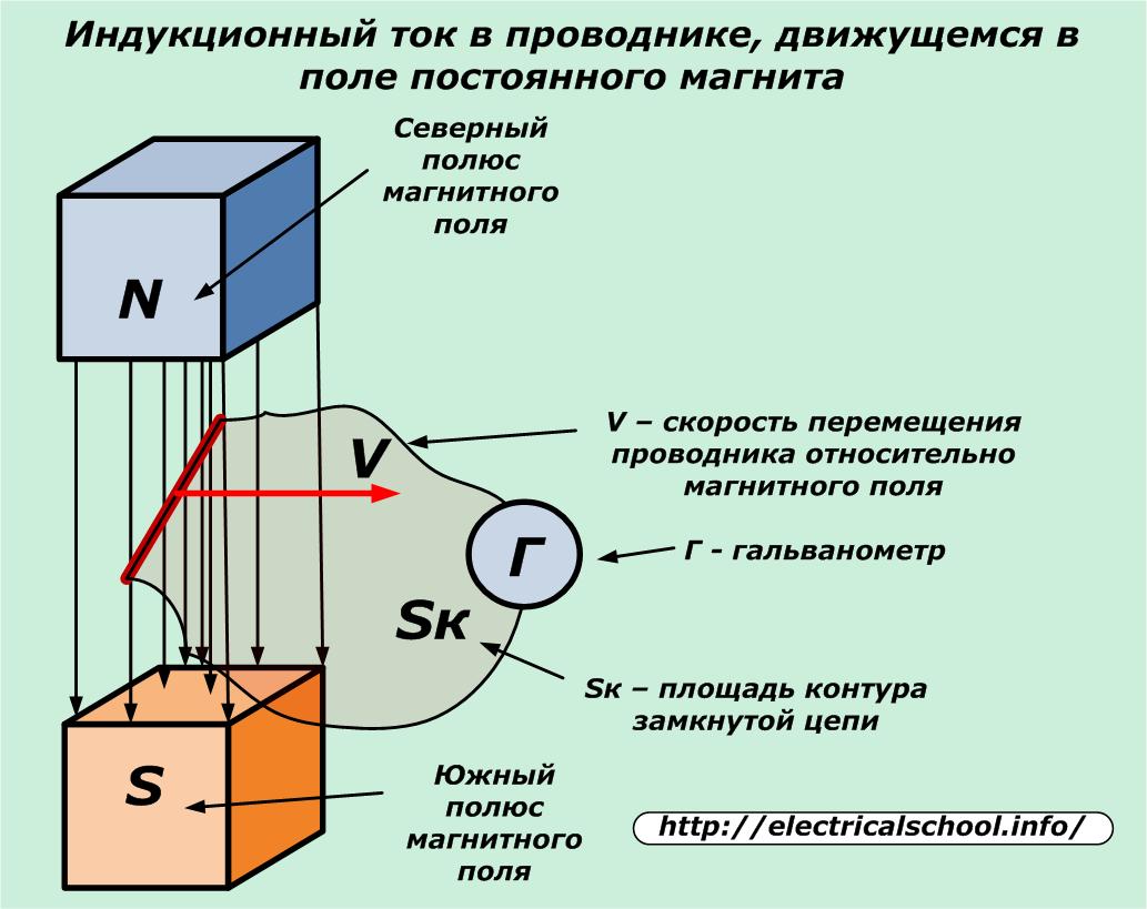
The same pattern is fully manifested when passing a closed loop magnetic field lines of a permanent magnet. Under the influence of EMF, an electric current is generated in the wire.
The magnetic flux in the considered case changes in the loop Sk created by a closed circuit.
Thus, the development created by Faraday made it possible to place a rotating conductive frame in a magnetic field.
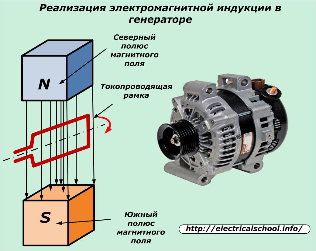
Then it was made of a large number of turns fixed in rotary bearings. At the ends of the coil, slip rings and brushes sliding on them were installed, and a load was connected through the housing terminals. The result is a modern alternator.
Its simpler design is created when the coil is fixed on a stationary housing and the magnetic system begins to rotate. In this case, the method of generating currents is due to electromagnetic induction not violated in any way.
The principle of operation of electric motors
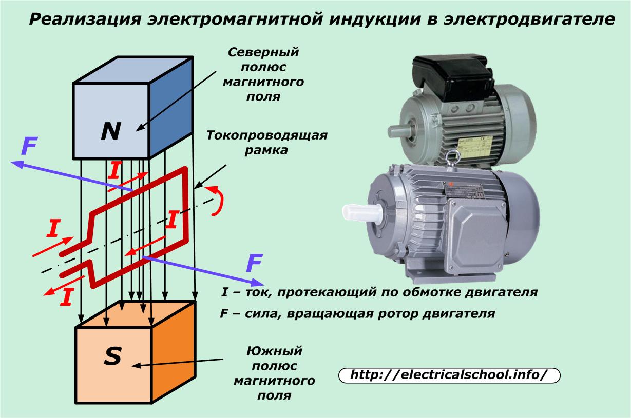
The law of electromagnetic induction, which Michael Faraday pioneered, allows for a variety of electric motor designs. They have a similar structure to generators: a movable rotor and stator that interact with each other due to rotating electromagnetic fields.
Electric current only passes through the stator winding of the electric motor. It induces a magnetic flux which affects the magnetic field of the rotor. As a result, forces arise that rotate the motor shaft. See on this topic — The principle of operation and the device of the electric motor
Electricity transformation
Michael Faraday determined the appearance of an induced electromotive force and an induced current in a nearby coil when the magnetic field in the neighboring coil changed.
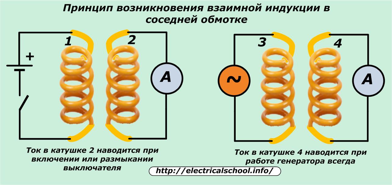
The current in the nearby coil is induced when the switch circuit is switched on in coil 1 and is always present during operation of the generator to coil 3.
The operation of all modern transformer devices is based on this property, the so-called mutual induction.
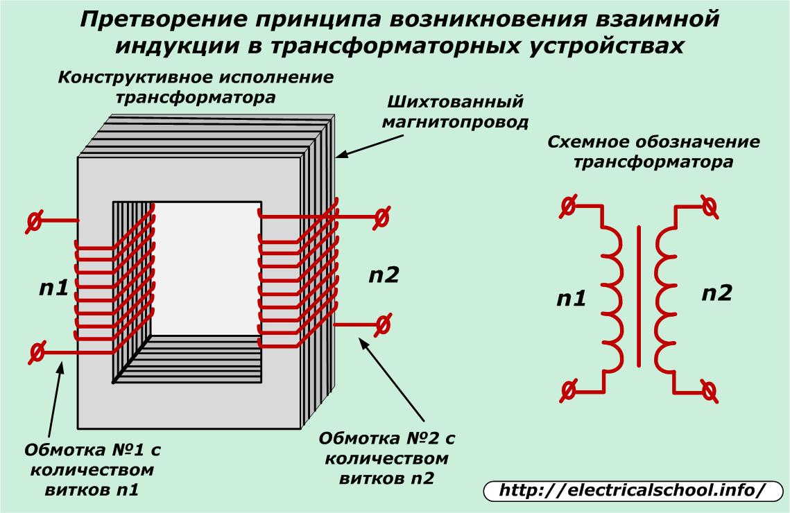
Transformers, due to mutual induction, transfer the energy of an alternating electromagnetic field from one coil to another, so a change occurs, a transformation of the voltage value at its input and output terminals.
The ratio of the number of turns in the windings determines the transformation coefficient, and the thickness of the wire, the construction and volume of the core material — the value of the transmitted power, the operating current.
Operation of inductors
The manifestation of electromagnetic induction is observed in the coil when the value of the current flowing in it changes. This process is called self-induction.
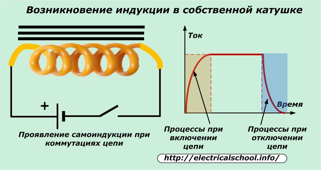
When the switch is turned on in the above diagram, the induced current changes the character of the linear increase in the operating current in the circuit, as well as during the turn-off.
When not a constant, but an alternating voltage is applied to the wire wound in the coil, then the value of the current, reduced by the inductive resistance, flows through it.Self-induction energy phase-shifts the current with respect to the applied voltage.
This phenomenon is used in chokes that are designed to reduce the large currents that occur under certain operating conditions. In particular, such devices are used in the circuit for lighting fluorescent lamps.
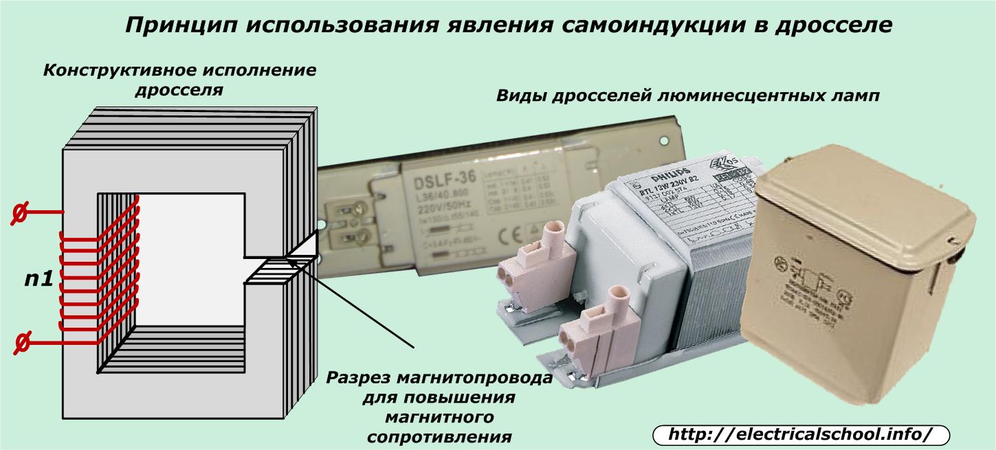
The feature of the design of the magnetic circuit of the choke is the cutout of the plates, which is created to further increase the magnetic resistance to the magnetic flux due to the formation of an air gap.
Chokes with split and adjustable magnetic circuit position are used in many radio and electrical devices. Quite often they can be found in the construction of welding transformers. They reduce the magnitude of the electric arc passed through the electrode to the optimal value.
Induction ovens
The phenomenon of electromagnetic induction is manifested not only in wires and coils, but also inside any massive metal objects. The currents induced in them are usually called eddy currents. During the operation of transformers and chokes, they cause heating of the magnetic circuit and the entire structure.
To prevent this phenomenon, the cores are made of thin metal sheets and insulated with a layer of varnish, which prevents the passage of induced currents.
In heating structures, eddy currents do not limit, but create the most favorable conditions for their passage. Induction ovens are widely used in industrial production to create high temperatures.
Electrotechnical measuring devices
A large class of induction devices continues to operate in electricity.Electric meters with a rotating aluminum disk similar to the construction of a power relay, damping dial systems, work on the principle of electromagnetic induction.
Gas magnetic generators
If, instead of a closed frame, a conductive gas, liquid or plasma moves in the field of a magnet, then the charges of electricity under the action of magnetic field lines will begin to deviate in strictly defined directions, forming an electric current. Its magnetic field on the mounted electrode contact plates induces an electromotive force. Under its action, an electric current is generated in the connected circuit to the MHD generator.
Thus, the law of electromagnetic induction manifests itself in MHD generators.
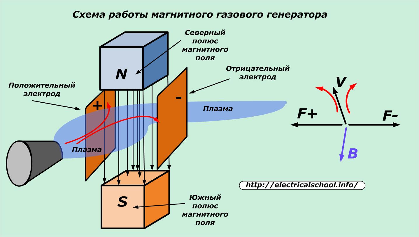
There are no complicated rotating parts like the rotor. This simplifies the design, allows you to significantly increase the temperature of the working environment and at the same time the efficiency of electricity generation. MHD generators operate as backup or emergency sources capable of generating significant flows of electricity for short periods of time.
Thus, the law of electromagnetic induction, substantiated at one time by Michael Faraday, continues to be relevant today.