What is a magnetic circuit and where is it used
 Two compound roots "magnet" and "conductor" connected by the letter "o" determine the purpose of this electrical device, created to reliably transmit the magnetic flux through a special conductor with minimal or in some cases certain losses.
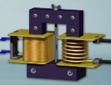
The electrical industry widely uses the interdependence of electric and magnetic energy, their transition from one state to another. Many transformers, chokes, contactors, relays, starters, electric motors, generators and other similar devices work on this principle.
Their design includes a magnetic circuit that transmits a magnetic flux excited by the passage of electric current to further convert electrical energy. It is one of the components of the magnetic system of electrical devices.
Magnetic core of an electrical product (device) (coil flux guide) — a magnetic system of an electrical product (device) or a set of several of its parts in the form of a separate structural unit (GOST 18311-80).
What is the magnetic core made of?
Magnetic characteristics
The substances that are included in its design can have different magnetic properties. They are usually classified into 2 types:
1. weakly magnetic;
2. highly magnetic.
To distinguish them, the term is used «Magnetic permeability µ», which determines the dependence of the created magnetic induction B (force) on the value of the applied force H.
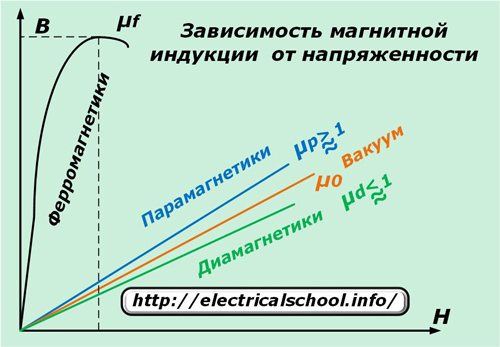
The above graph shows that ferromagnets have strong magnetic properties, while they are weak in paramagnets and diamagnets.
However, the induction of ferromagnets with a further increase in voltage begins to decrease, having a pronounced point with a maximum value that characterizes the moment of saturation of the substance. It is used in the calculation and operation of magnetic circuits.
After the termination of the action of voltage, a part of the magnetic properties remains with the substance, and if an opposite field is applied to it, then a part of its energy will be spent in overcoming this fraction.
Therefore, in alternating electromagnetic field circuits there is an induction lag from the applied force. A similar dependence on the magnetization of the substance of ferromagnets is characterized by a graph called hysteresis.
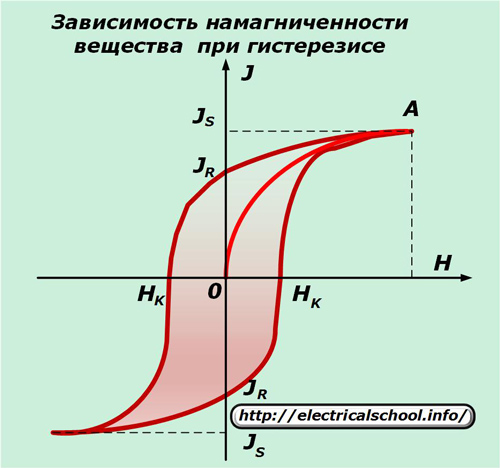
On it, the points Hk show the width of the contour that characterizes the residual magnetism (coercive force). According to their size, ferromagnets are divided into two categories:
1. soft, characterized by a narrow loop;
2. hard, with high coercive force.
The first category includes soft alloys of iron and permola. They are used to make cores for transformers, electric motors and alternators because they create a minimal energy expenditure to reverse the magnetization.
Hard ferromagnets made of carbon steels and special alloys are used in various permanent magnet designs.
When choosing a material for a magnetic circuit, losses are taken into account for:
-
hysteresis;
-
eddy currents generated by the action of the EMF induced by the magnetic flux;
-
consequence due to magnetic viscosity.
Materials (edit)
Characteristics of alloys
For AC magnetic circuit designs, special grades of sheet or coiled thin-walled steel are produced with varying degrees of alloying additions, which are produced by cold or hot rolling. Also, cold rolled steel is more expensive but has less induction losses.
Steel sheets and coils are machined into plates or strips. They are covered with a layer of varnish for protection and insulation. Double-sided coverage is more reliable.
For relays, starters and contactors operating in DC circuits, the magnetic cores are cast in solid blocks.
AC circuits
Magnetic cores of transformers
Single-phase devices
Among them, two types of magnetic circuits are common:
1. stick;
2. Armored.
The first type is made with two rods, on each of which two coils with high or low voltage coils are separately placed. If a LV and LV coil is placed on the bar, then large energy dissipation flows occur and the reactance component increases.
The magnetic flux passing through the rods is closed by the upper and lower yoke.
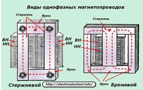
The armored type has a rod with coils and yokes from which the magnetic flux splits into two halves. Therefore, its area is twice the cross-section of the yoke.Such structures are more often found in low-power transformers, where large thermal loads are not created on the structure.
Power transformers require a large cooling surface with windings due to the conversion of higher loads. The consolidated scheme is more suitable for them.
Three-phase devices
For them, you can use three single-phase magnetic circuits located at a third of the circumference, or collect coils of common iron in their cages.
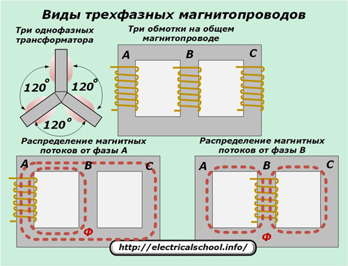
If we consider a common magnetic circuit of three identical structures located at an angle of 120 degrees, as shown in the upper left corner of the picture, then inside the central rod the total magnetic flux will be balanced and equal to zero.
In practice, however, a simplified design located in the same plane, when three different windings are located on a separate rod, is more often used. In this method, the magnetic flux from the end coils passes through the large and small rings, and from the middle - through two adjacent ones. Due to the formation of an uneven distribution of distances, a certain imbalance of magnetic resistances is created.
It imposes separate restrictions on design calculations and some modes of operation, especially idling. But in general, such a scheme of the magnetic circuit is widely used in practice.
The magnetic circuits shown in the above photos are made of plates, and coils are placed on the assembled rods. This technology is used in automated factories with a large machinery park.
In small industries, manual assembly technology can be used due to tape blanks, when a coil is initially made with a coiled wire, and then a magnetic circuit is installed around it from a tape of transformer iron with successive turns.
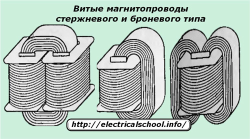
Such twisted magnetic circuits are also created according to the bar and armored type.
For strip technology, the allowable thickness of the material is 0.2 or 0.35 mm, and for installation with plates, 0.35 or 0.5 or even more can be chosen. This is due to the need to tightly wind the tape between layers, which is difficult to do manually when working with thick materials.
If, when winding the tape on a reel, its length is not enough, then it is allowed to join an extension to it and reliably press it with a new layer. In the same way, plates of rods and yokes are assembled in lamellar magnetic circuits. In all these cases, the joints must be made with minimum dimensions, since they affect the total reluctance and energy loss in general.
For accurate work, the creation of such joints is tried to be avoided, and when it is impossible to exclude them, then they use edge grinding, achieving a close fit of the metal.
When manually assembling a structure, it is quite difficult to precisely orient the plates to each other. Therefore, holes were drilled in them and pins were inserted, which ensured good centering. But this method slightly reduces the area of the magnetic circuit, distorts the passage of force lines and magnetic resistance in general.
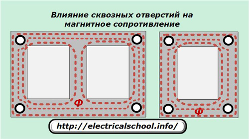
Large automated enterprises specializing in the production of magnetic cores for precision transformers, relays, starters have abandoned the perforating holes inside the plates and use other assembly technologies.
Clad and front constructions
Magnetic cores created on the basis of plates can be assembled by separately preparing the yoke bars and then mounting coils with coils, as shown in the photo.
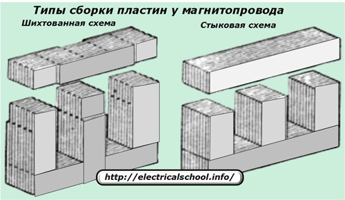
A simplified butt assembly diagram is shown to the right. It can have a serious drawback — "fire in steel", which is characterized by the appearance eddy currents in the core to the critical value as shown in the picture below on the left with a wavy red line. This creates an emergency.
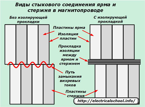
This defect is eliminated with an insulating layer, which significantly affects the increase of the magnetizing flux. And these are unnecessary losses of energy.
In some cases, it is necessary to increase this gap to increase reactivity. This technique is used in inductors and chokes.
For the reasons listed above, the face assembly scheme is used in non-critical structures. For accurate operation of the magnetic circuit, a laminated plate is used.
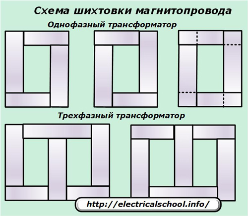
Its principle is based on a clear distribution of the layers and the creation of equal gaps in the rod and the yoke in such a way that during assembly all created cavities are filled with minimal joints. In this case, the plates of the rod and the yoke are intertwined with each other, forming a strong and rigid structure.
The previous photo above shows a laminated method of connecting rectangular plates.However, slanted structures, usually created at 45 degrees, have lower magnetic energy losses. They are used in powerful magnetic circuits of power transformers.
The photo shows the assembly of several inclined plates with partial unloading of the overall structure.
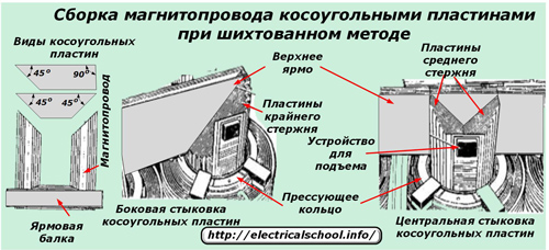
Even with this method, it is necessary to monitor the quality of the support surfaces and the absence of unacceptable gaps in them.
The method of using inclined plates ensures minimal losses of magnetic flux in the corners of the magnetic circuit, but significantly complicates the production process and assembly technology. Due to the increased complexity of the work, it is used very rarely.
The laminated assembly method is more reliable. The design is robust, requires fewer parts and is assembled using a pre-prepared method.
With this method, a common structure is created from the plates. After the complete assembly of the magnetic circuit, it becomes necessary to install the coil on it.
To do this, it is necessary to disassemble the already assembled upper yoke, successively removing all its plates. In order to eliminate such an unnecessary operation, the technology of assembling a magnetic circuit was developed directly inside the prepared windings with coils.
Simplified models of laminated structures
Low power transformers often do not require precise magnetic control. For them, blanks are created using stamping methods according to prepared templates, followed by coating with insulating varnish and most often on one side.
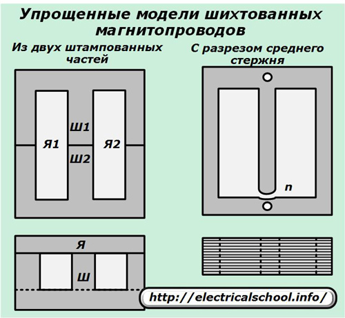
The left magnetic circuit assembly is created by inserting blanks into the coils above and below, and the right one allows you to bend and insert the center rod into the inner coil hole. In these methods, a small air gap is formed between the support plates.
After assembling the set, the plates are tightly pressed by the fasteners. To reduce eddy currents with magnetic losses, a layer of insulation is applied to them.
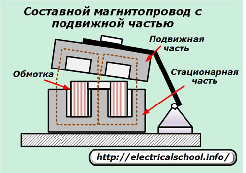
Characteristics of magnetic circuits of relays, starters
The principles of creating a path for the passage of the magnetic flux remained the same. Only the magnetic circuit is divided into two parts:
1. movable;
2. permanently fixed.
When a magnetic flux occurs, the movable armature, together with the contacts fixed on it, is attracted by the principle of an electromagnet, and when it disappears, it returns to its original state under the action of mechanical springs.
Short circuit
Alternating current is constantly changing in magnitude and amplitude. These changes are transmitted to the magnetic flux and the moving part of the armature, which can hum and vibrate. To eliminate this phenomenon, the magnetic circuit is separated by inserting a short circuit.
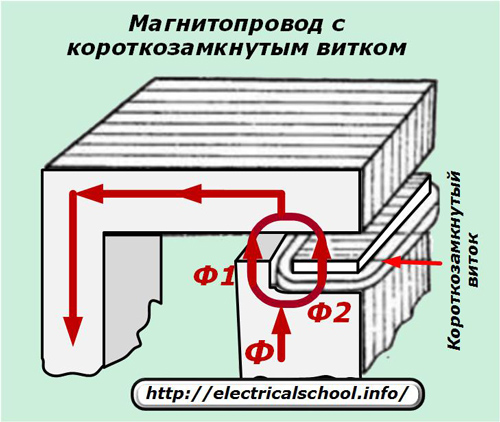
A bifurcation of the magnetic flux and a phase shift of one of its parts are formed in it. Then, when crossing the zero point of one branch, a vibration-preventing force acts in the second, and vice versa.
Magnetic cores for DC devices
In these circuits, there is no need to deal with the harmful effects of eddy currents, which manifest themselves in harmonic sinusoidal oscillations.For magnetic cores, thin plate assemblies are not used, but they are made with rectangular or rounded parts by the method of one-piece castings.
In this case, the core on which the coil is mounted is round, and the housing and yoke are rectangular.
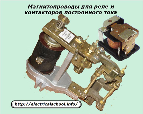
To reduce the initial pulling force, the air gap between the separated parts of the magnetic circuit is small.
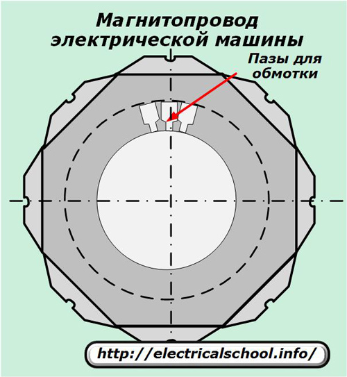
Magnetic circuits of electrical machines
The presence of a movable rotor that rotates in the stator field requires special characteristics electric motor designs and generators. Inside them, it is necessary to arrange the coils through which the electric current flows, so as to ensure the minimum dimensions.
For this purpose, cavities are made for laying wires directly in the magnetic circuits. To do this, immediately when stamping the plates, channels are created in them, which after assembly are ready lines for the coils.
Thus, the magnetic circuit is an integral part of many electrical devices and serves to transmit magnetic flux.