Controlled rectifiers - device, schemes, principle of operation
Controlled rectifiers are used to regulate the output voltage in rectified AC circuits. Along with other methods of controlling the output voltage after the rectifier, such as LATR or rheostat, a controlled rectifier allows achieving greater efficiency with high circuit reliability, which cannot be said for regulation using LATR or rheostat regulation.
Using controlled valves is more progressive and much less cumbersome. Thyristors are best suited for the role of controlled valves.
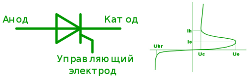
In the initial state, the thyristor is locked and has two possible stable states: closed and open (conducting).If the source voltage is higher than the lower operating point of the thyristor, then when a current pulse is applied to the control electrode, the thyristor will go into a conducting state and subsequent pulses applied to the control electrode will not affect the anode current in any way , that is, the control circuit is responsible only for opening the thyristor, but not for closing it. It can be argued that thyristors have a significant increase in power.
To turn off the thyristor, it is necessary to reduce its anode current so that it becomes less than the holding current, which is achieved by lowering the supply voltage or increasing the load resistance.
Thyristors in the open state are capable of conducting currents up to several hundred amperes, but at the same time, thyristors are quite inertial. The turn-on time of the thyristor is from 100 ns to 10 μs, and the turn-off time is ten times longer - from 1 μs to 100 μs.
In order for the thyristor to work reliably, the rate of rise of the anode voltage should not exceed 10 — 500 V / μs, depending on the component model, otherwise false switching may occur due to the action of the capacitive current through the pn junctions.
To avoid false switching, the control electrode of the thyristor is always shunted with a resistor, the resistance of which is usually in the range of 51 to 1500 ohms.
In addition to thyristors, others are used to regulate the output voltage in rectifiers. semiconductor devices: triacs, dinistors and lock-in thyristors. Dynistors are turned on by the voltage applied to the anode, and they have two electrodes, like diodes.
Triacs are distinguished by the ability to include control pulses at least relative to the anode, at least relative to the cathode, but all these devices, like thyristors, are turned off by reducing the anode current to a value below the holding current. As for lockable thyristors, they can be locked by applying a current of reverse polarity to the control electrode, but the gain at turn-off is ten times lower than at turn-on.
Thyristors, triacs, dinistors, controllable thyristors — all these devices are used in power supplies and in automation circuits to regulate and stabilize voltage and power, as well as for protection purposes.
As a rule, thyristors are used instead of diodes in controlled rectification circuits. In single-phase bridges, the switching point of the diode and the switching point of the thyristor are different, there is a phase difference between them, which can be reflected by considering the angle.
The DC component of the load voltage is nonlinearly related to this angle because the supply voltage is inherently sinusoidal. The DC component of the load voltage connected after the regulated rectifier can be found by the formula:
The control characteristic of a thyristor-controlled rectifier shows the dependence of the output voltage on the load from the phase (on the angle of switching on) of the bridge:
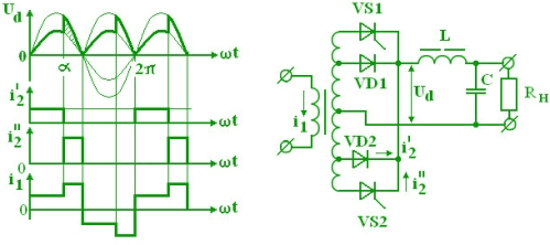
With an inductive load, the current through the thyristors will have a rectangular shape, and at an angle greater than zero, the current will be drawn due to the action of self-induced EMF from the inductance of the load.
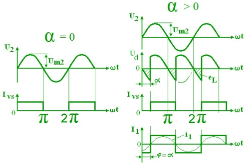
In this case, the fundamental harmonic of the grid current will be shifted relative to the voltage by a certain angle. To remove the clamping, a zero diode is used, through which the current can be closed and give an offset of less than half the angle of the bridge.
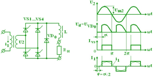
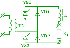
To reduce the number of semiconductors, they resort to an asymmetrical controllable rectifier circuit, where a pair of diodes replaces a neutral diode and the result is the same.
Amplifier circuits also allow the use of thyristors. Such schemes allow you to achieve greater efficiency. The minimum voltage is given by diodes, and the increased voltage is supplied through thyristors. In the case of the greatest consumption, the diodes are closed all the time, and the switching angle of the thyristor is always 0. The disadvantage of the circuit is the need for an additional transformer winding.