Three-phase bridge rectifier - principle of operation and circuits
If single-phase or bridge single-phase rectifiers are used for low-power DC circuits, then three-phase rectifiers are sometimes required to supply higher power loads.
Three-phase rectifiers allow obtaining high values of constant currents with low levels of output voltage ripple, which has the effect of reducing the requirements for the characteristics of the smoothing output filter.
So, first, consider the single-phase three-phase rectifier shown in the figure below:
In the single-ended circuit shown in the figure, only three are connected to the terminals of the secondary windings of a three-phase transformer. rectifier… The load is connected to a circuit between the common point where the cathodes of the diodes converge and the common terminal of the three secondary windings of the transformer.
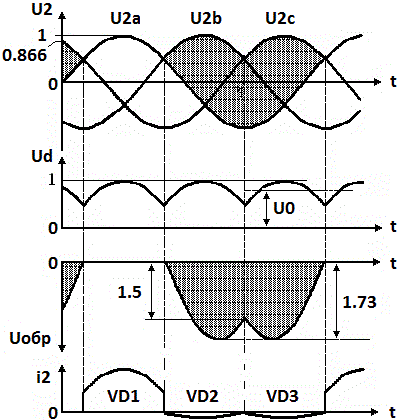
Let us now consider the time diagrams of currents and voltages occurring in the secondary windings of the transformer and of one of the diodes of a three-phase single-ended rectifier:
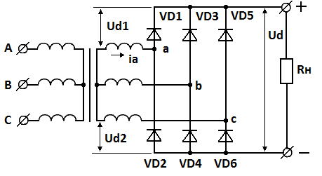
Some DC devices require a higher supply voltage than the single circuit above can provide. Therefore, in some cases a three-phase push-out circuit is more suitable. Its schematic diagram is shown in the figure below.
As we already noted, the filter requirements are reduced, you can see this in the charts. This circuit is known as a three-phase Larionov bridge rectifier:
Now look at the diagrams and compare them to the unit diagram. The output voltage in the bridge circuit is easily represented as the sum of the voltages of two single rectifiers operating in opposite phases. Voltage Ud = Ud1 + Ud2. The number of output phases is obviously greater and the frequency of the network waves is higher.
In this particular case, six DC phases instead of the three that were in a single circuit. Therefore, the requirements for the anti-aliasing filter are reduced, and in some cases it can be removed altogether.
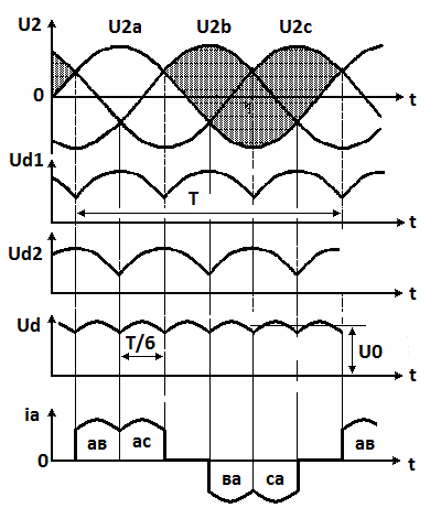
Three phases of the windings combined with two half-cycles of rectification give a fundamental wave frequency equal to six times the grid frequency (6 * 50 = 300). This can be seen from the voltage and current diagrams.
The bridge connection can be seen as a combination of two single-phase three-phase zero-point circuits, with diodes 1, 3 and 5 being the cathode group of diodes and diodes 2, 4 and 6 being the anode group.
The two transformers appear to be combined into one. At any moment the current flows through the diodes, two diodes are simultaneously involved in the process — one from each group.
The cathode diode opens to which a higher potential is applied relative to the anodes of the opposite group of diodes, and in the anode group exactly that of the diodes to which the potential is applied lower relative to the cathodes of the diodes of the cathode group opens.
The transition of the working time intervals between the diodes occurs at the moments of natural switching, the diodes work in order. As a result, the potential of common cathodes and common anodes can be measured by the upper and lower envelopes of the phase voltage graphs (see diagrams).
The instantaneous values of the rectified voltages are equal to the potential difference between the cathode and anode groups of the diodes, that is, the sum of the ordinates in the diagram between the envelopes. The forward current of the secondary windings is shown in the resistive load diagram.
Similarly, more than six constant voltage phases can be obtained from a three-phase transformer: nine, twelve, eighteen and even more. The more phases (the more diode pairs) in the rectifier, the lower the ripple level of the output voltage. Here, look at the circuit with 12 diodes:
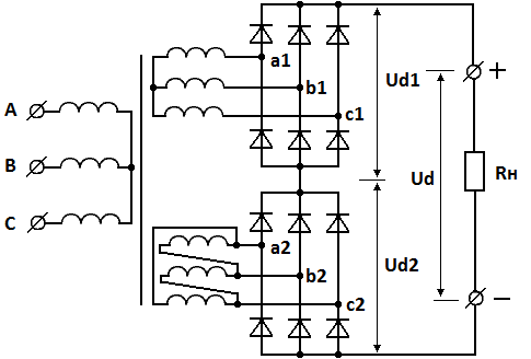
Here, a three-phase transformer contains two three-phase secondary windings, one of the groups is combined in a «delta» circuit, the other in a «star». The number of turns in the coils of the groups differ by 1.73 times, which makes it possible to obtain the same voltage values from the "star" and from the "delta".
In this case, the phase shift of the voltages in these two groups of secondary windings relative to each other is 30 °.Since the rectifiers are connected in series, the output voltage is summed and the load ripple frequency is now 12 times higher than the mains frequency, while the ripple level is lower.
See also:
Controlled rectifiers - device, schemes, principle of operation
The most common AC to DC rectification schemes