Triangles of voltages, resistances and powers
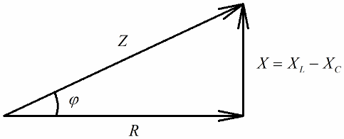
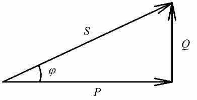
Anyone who has an idea of vector diagrams will easily notice that a right-angled voltage triangle can be very clearly distinguished on them, each side of which reflects: the total voltage of the circuit, the voltage of the active resistance and the voltage on reactance.
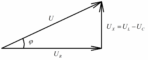
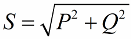
In accordance with the Pythagorean theorem, the relationship between these voltages (between the total voltage of the circuit and the voltage of its sections) will look like this:
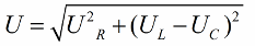
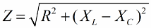
If the next step is to divide the values of these voltages by the current (the current flows through all sections of the series circuit equally), then by Ohm's Law we get the resistance values, that is, now we can talk about a right-angled triangle of resistances:
In a similar way (as in the case of voltages), using the Pythagorean theorem, it is possible to establish a relationship between the impedance of the circuit and the reactances. The relationship will be expressed by the following formula:
Then we multiply the resistance values by the current, in fact we will increase each side of the right triangle by a certain number of times. As a result, we get a right-angled triangle with capacities:
The active power released at the active resistance of the circuit associated with the irreversible conversion of electrical energy (into heat, in the performance of work in the installation) will be clearly related to the reactive power involved in the reversible conversion of energy (the creation of magnetic and electric fields in coils and capacitors) and with full power supplied to the electrical installation.
Active power is measured in watts (W), reactive power — in varis (VAR — volt-ampere reactive), total — in VA (volt-ampere).
According to the Pythagorean theorem, we have the right to write:
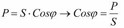
Let's now pay attention to the fact that in the power triangle there is an angle phi, the cosine of which is easy to determine primarily by active power and apparent power. The cosine of this angle (cos phi) called power factor. It shows how much of the total power is accounted for when doing useful work in an electrical installation and is not returned to the grid.
Obviously, a higher power factor (maximum one) indicates a higher conversion efficiency of the energy delivered to the plant for operation. If the power factor is 1, then all the energy supplied is used to do work.
The obtained ratios allow the expression of the current consumption of the installation in terms of power factor, active power and network voltage:
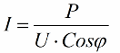
So, the smaller the cosine phi, the more current is required by the network to do a certain job. In practice, this factor (maximum network current) limits the transmission capacity of the transmission line and therefore, the lower the power factor, the greater the line load and the lower the useful bandwidth (the low cosine phi leads to restriction ). Joule losses in power lines with decreasing cosine phi can be seen from the following formula:
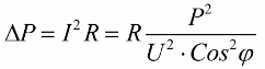
On the active resistance R of the transmission line, the losses increase the more the higher the current I, even though it is reactive to the load. Therefore, we can say that with a low power factor, the cost of electricity transmission simply increases. This means that increasing cosine phi is an important national economic task.
It is desirable that the reactive component of the total power should approach zero. To do this, it would be good to always use electric motors and transformers at full load and turn them off at the end of use so that they do not idle. At no load, motors and transformers have a very low power factor. One way to increase cosine phi in users is to use capacitor banks and synchronous compensators.