Principles of thyristor and triac control
Let's start with the simplest schemes. In the simplest case, to control a thyristor, it is enough to briefly supply a constant current of a certain value to its control electrode. The mechanism for supplying this current can be shown schematically by picturing a switch that closes and supplies power, like the output stage of a chip or transistor.
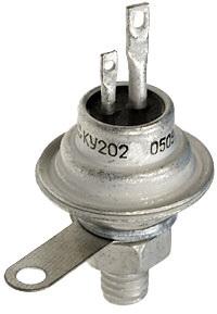
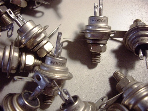
This is a seemingly simple method, but the power of the control signal here is required to be significant. So, under normal conditions for the triac KU208, this current should be at least 160 mA, and for the trinistor KU201 it should be at least 70 mA. Thus, at a voltage of 12 volts and with an average current of, say, 115 mA, the control power will now be 1.4 W.
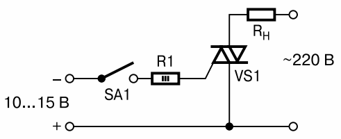
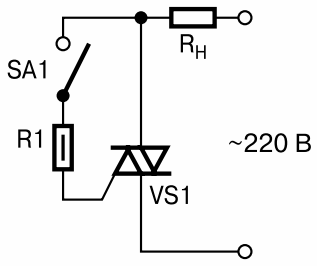
The polarity requirements of the control signal are as follows: the SCR requires a control voltage that is positive with respect to the cathode, and the triac (balanced thyristor) requires the same polarity as the anode current, or negative for each of the half cycles.
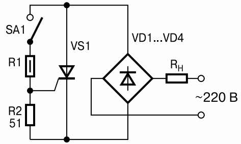
The control electrode of the triac is not shunted, the trinistor is manipulated with a 51 ohm resistor.Modern thyristors require less and less control current, and very often you can find circuits where the control current of SCRs is reduced to about 24 mA, and for triacs to 50 mA.
It may happen that a sharp decrease in the current in the control circuit will affect the reliability of the device, so sometimes developers have to choose thyristors separately for each circuit. Otherwise, to open the low-current thyristor, its anode voltage would have to be high at that moment, leading to harmful inrush current and interference.
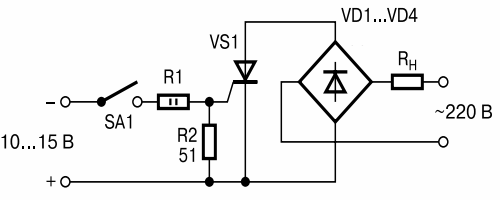
The lack of control according to the simplest scheme described above is obvious: there is a permanent galvanic connection of the control circuit with the electrical circuit. Triacs in some circuits allow one of the terminals of the control circuit to be connected to the neutral wire. SCRs allow such a solution only by adding a diode bridge to the load circuit.
As a result, the power supplied to the load is halved because the voltage is supplied to the load in only one of the periods of the mains sine wave. In practice, we have the fact that circuits with thyristor control of direct current without galvanic isolation of nodes are almost never used, except when the control, for some good reason, must be carried out in this way.
A common thyristor control solution is where the voltage is applied to the gate electrode directly from the anode through a resistor by closing the switch for a few microseconds. The key here can be a high voltage bipolar transistor, a small relay, or a photoresistor.
This approach is acceptable at relatively high anode voltage, it is convenient and simple even if the load contains a reactive component. But there is also a drawback: ambiguous requirements for the current-limiting resistor, which must be small in nominal value, so that the thyristor turns on closer to the beginning of the half-cycle of the sine wave when it is first turned on, not at zero mains voltage (in the absence of synchronization), 310 volts can also come to it, but the current through the switch and through the control electrode of the thyristor should not exceed the maximum allowable values for them.
The thyristor itself will open to the voltage Uop = Iop * Rlim. As a result, noise will occur and the load voltage will decrease slightly. The calculated resistance of the resistor Rlim is reduced by the value of the resistance of the load circuit (including its inductive component), which happens to be connected in series with the resistor at the time of switching on.
But in the case of heating devices, the fact that in a cold state their resistance is ten times less than in a working heated one is taken into account. By the way, due to the fact that in triacs the turn-on current for positive and negative half-waves may differ slightly, a small constant component may appear on the load.
The turn-on time of the SCR is usually not more than 10 μs, therefore, for economical load power control, a pulse train with a duty cycle of 5, 10, or 20 can be applied for frequencies of 20, 10, and 5 kHz, respectively. The power will decrease from 5 to 20 times.
The disadvantage is the following: the thyristor can turn on, and not at the beginning of the half-cycle.It is full of waves and noise. And yet, even if the turn-on occurs just before the beginning of the voltage rise from zero, at this moment the current of the control electrode may not yet reach the holding value, then the thyristor will turn off immediately after the end of the pulse.
As a result, the thyristor will first turn on and off for short intervals until finally the current takes on a sinusoidal shape. For loads with an inductive component, the current may not reach the holding value, which imposes a lower limit on the duration of the control pulses, and the power consumption will not decrease much.
Separation of the control circuit from the network is provided by the so-called impulse start, which can be easily carried out by installing a small isolation transformer on a ferrite ring with a diameter of less than 2 cm. It is important that the isolation voltage of such a transformer should be high, and not just like any industrial pulse transformer...
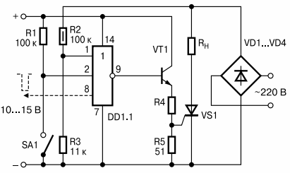
In order to significantly reduce the power required for control, it will be necessary to resort to more precise control. The gate current must be turned off just as the thyristor is turned on. When the switch is closed, the thyristor turns on, and when the thyristor begins to conduct current, the microcircuit stops supplying current through the control electrode.
This approach really saves the energy needed to drive the thyristor. If the switch is currently closed, the anode voltage is still not enough, the thyristor will not be opened by the microcircuit (the voltage should be slightly more than half the supply voltage of the microcircuit). The switch-on voltage is adjustable selection of decoupling resistors.
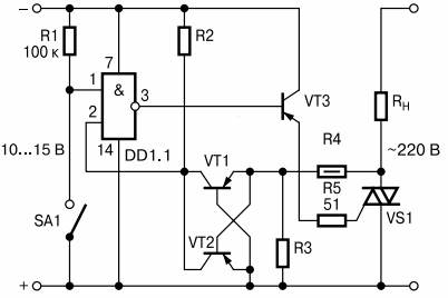
To control the triac in this way, it is necessary to track the polarity, so a block of a pair of transistors and three resistors is added to the circuit, which fixes the moment when the voltage crosses zero. More complex schemes are beyond the scope of this article.