Linear voltage stabilizers — purpose, basic parameters and switching circuits
Perhaps today, no electronic board can do without at least one source of constant constant voltage. And very often linear voltage regulators in the form of microcircuits serve as such sources. Unlike a rectifier with a transformer, where the voltage in one way or another depends on the load current and can vary slightly for various reasons, an integrated microcircuit - a stabilizer (regulator) is able to provide a constant voltage in a precisely defined range of load currents .
These microcircuits are built on the basis of field-effect or bipolar transistors, continuously operating in active mode. In addition to the regulating transistor, a control circuit is also installed on the crystal of the microcircuit of the linear stabilizer.
Historically, before it became possible to manufacture such stabilizers in the form of microcircuits, there was a question of solving the problem of temperature stability of parameters, since with heating during operation, the parameters of microcircuit nodes will change.
The solution came in 1967, when the American electronics engineer Robert Widlar proposed a stabilizer circuit in which a regulating transistor would be connected between an unregulated input voltage source and a load, and an error amplifier with a temperature-compensated reference voltage would be present in the control circuit. As a result, the popularity of linear integrated stabilizers in the market jumped rapidly.
Check out the photo below. Shown here is a simplified diagram of a linear voltage regulator (such as the LM310 or 142ENxx). In this scheme, a non-inverting negative-voltage feedback operational amplifier, using its output current, controls the degree of unlocking of the regulating transistor VT1, connected in a circuit with a common collector - emitter follower.
The op-amp itself is powered by the input source in the form of a unipolar positive voltage. And although the negative voltage is not suitable for supply here, the supply voltage of the op-amp can be doubled without problems, without fear of overload or damage.
The conclusion is that the deep negative feedback neutralizes the instability of the input voltage, the value of which in this circuit can reach 30 volts. So, fixed output voltages range from 1.2 to 27 volts, depending on the chip model.
The stabilizer microcircuit traditionally has three pins: input, common and output.The figure shows a typical circuit of a differential amplifier as part of a microcircuit to obtain a reference voltage Zener diode applied.

In low-voltage regulators, the voltage reference is obtained at the gap, as Widlar first proposed in his first linear integrated regulator, the LM109. A divider is installed in the negative feedback circuit of resistors R1 and R2, by the action of which the output voltage turns out to be simply proportional to the reference voltage in accordance with the formula Uout = Uvd (1 + R2 / R1).
Resistor R3 and transistor VT2 built into the stabilizer serve to limit the output current, so if the voltage on the current limiting resistor exceeds 0.6 volts, then transistor VT2 will open immediately, which will cause the base current of the main control transistor VT1 to be limited. It turns out that the output current in the normal mode of operation of the stabilizer is limited to 0.6 / R3. The power dissipated by the regulating transistor will depend on the input voltage and will be equal to 0.6 (Uin — Uout) / R3.
If for some reason a short circuit occurs at the output of the integrated stabilizer, then the dissipated power on the crystal should not be left as before, proportional to the voltage difference and inversely proportional to the resistance of the resistor R3. Therefore, the circuit contains protective elements — zener diode VD2 and resistor R5, the operation of which sets the level of current protection depending on the difference in voltage Uin -Uout.
In the above graph, you can see that the maximum output current depends on the output voltage, thus the microcircuit of the linear stabilizer is reliably protected from overload.When the voltage difference Uin-Uout exceeds the stabilization voltage of the zener diode VD2, the divider of the resistors R4 and R5 will create enough current in the base of the transistor VT2 to turn it off, which in turn will cause the base current limit to increase of the regulating transistor VT1.
The latest models of linear regulators, such as the ADP3303, are equipped with thermal overload protection when the output current drops sharply when the crystal is heated to 165 ° C. The capacitor in the above diagram is needed to equalize the frequency.
By the way, about the capacitors. It is customary to connect capacitors with a minimum capacity of 100 nf to the input and output of the integrated stabilizers to avoid false activation of the internal circuits of the microcircuit. Meanwhile, there are so-called capless stabilizers, such as the REG103, for which there is no need to install stabilizing capacitors at the input and output.
In addition to linear stabilizers with a fixed output voltage, there are also stabilizers with an adjustable output voltage for stabilization. In them, the divider of the resistors R1 and R2 is missing, and the base of the transistor VT4 is brought out to a separate leg of the chip for connecting an external divider, such as in the 142EN4 chip.
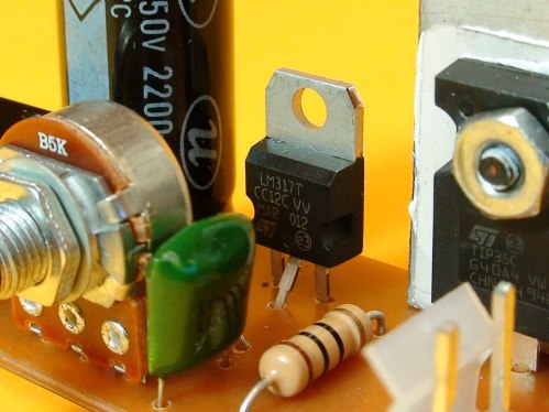
More modern stabilizers, in which the current consumption of the control circuit is reduced to several tens of microamps, such as the LM317, have only three pins.To be fair, we note that today there are also high-precision voltage regulators such as the TPS70151, which, due to the presence of several additional pins, make it possible to apply voltage drop protection to the connecting wires, load discharge control, etc.
Above we talked about positive voltage stabilizers, relative to the common wire. Similar schemes are also used to stabilize negative voltages, it is enough only to galvanically isolate the output voltage of the input from the common point. The output pin is then connected to the common output point, and the negative output point will be the input minus point connected to the common point of the stabilizer chip. Negative polarity voltage regulators like the 1168ENxx are very convenient.
If it is necessary to obtain two voltages at once (positive and negative polarity), then for this purpose there are special stabilizers that give a symmetrically stabilized positive and negative voltage at the same time, it is enough just to apply positive and negative input voltages to the inputs. An example of such a bipolar stabilizer is the KR142EN6.
The figure above is a simplified diagram of it. Here, the differential amplifier # 2 drives the transistor VT2, so the equality -UoutR1 / (R1 + R3) = -Uop is observed. And amplifier #1 controls the transistor VT1 so that the potential at the junction of the resistors R2 and R4 remains zero. If at the same time resistors R2 and R4 are equal, then the output voltage (positive and negative) will remain symmetrical.
For independent adjustment of the balance between two (positive and negative) output voltages, you can connect additional trimming resistors to the special pins of the microcircuit.
The smallest voltage drop characteristic of the above linear regulatory circuits is 3 volts. This is quite a lot for battery or battery powered devices and it is generally desirable to minimize the voltage drop. For this purpose, the output transistor is made pnp type so that the collector current of the differential stage is simultaneously with the base current of the regulating transistor VT1. The minimum voltage drop will now be on the order of 1 volt.
Negative voltage regulators operate in a similar manner with minimal droop. For example, the 1170ENxx series regulators have a voltage drop of about 0.6 volts and do not overheat when made in the TO-92 case at load currents up to 100 mA. The stabilizer itself consumes no more than 1.2 mA.
Such stabilizers are classified as low droop. Even lower voltage drop is achieved on MOSFET-based regulators (about 55 mV at 1 mA chip current consumption) such as the MAX8865 chip.
Some stabilizer models are equipped with shutdown pins to reduce the power consumption of the devices in standby mode — when a logic level is applied to this pin, the consumption of the stabilizer is reduced to almost zero (line LT176x).
Speaking about integral linear stabilizers, they note their characteristics, as well as dynamic and accurate parameters.
The accuracy parameters are stabilization factor, output voltage setting accuracy, output impedance and voltage temperature coefficient. Each of these parameters is listed in the documentation; they are related to the accuracy of the output voltage depending on the input voltage and the current temperature of the crystal.
Dynamic parameters such as ripple suppression ratio and output impedance are set for different frequencies of load current and input voltage.
Performance characteristics such as input voltage range, rated output voltage, maximum load current, maximum power dissipation, maximum input and output voltage difference at maximum load current, no-load current, operating temperature range, all these parameters affect on the choice of one or the other.stabilizer for a certain circuit.
Characteristics of linear voltage regulators
Here are the typical and most popular circuits for including linear stabilizers:
If it is necessary to increase the output voltage of a linear stabilizer with a fixed output voltage, a zener diode is added in series to the common terminal:
To maximize the permissible output current, a more powerful transistor is connected in parallel with the stabilizer, turning the regulating transistor inside the microcircuit into a part of a composite transistor:

If it is necessary to stabilize the current, the voltage stabilizer is turned on according to the following scheme.
In this case, the voltage drop across the resistor will be equal to the stabilization voltage, which will lead to significant losses if the stabilization voltage is high.In this regard, it will be more appropriate to choose a stabilizer for the lowest possible output voltage, such as the KR142EN12 for 1.2 volts.