Main characteristics of triacs
All semiconductor devices are based on junctions, and if a three-junction device is a thyristor, then two three-junction devices connected in parallel in a common housing are already triac, that is, a symmetrical thyristor. In the English-language literature it is called «TRIAC» - AC triode.
One way or another, the triac has three outputs, two of which are power, and the third is a control or gate (English GATE). At the same time, the triac does not have a specific anode and cathode, since each of the power electrodes at different times can act as both an anode and a cathode.
Because of these characteristics, triacs are very widely used in alternating current circuits. In addition, triacs are inexpensive, have a long service life and do not cause sparks compared to mechanical switching relays, and this ensures their continuous demand.
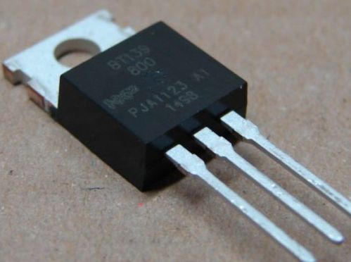
Let's look at the main characteristics, that is, the main technical parameters of triacs, and explain what each of them means. We will consider the example of a fairly common triac BT139-800, which is often used in various types of regulators.So, the main characteristics of the triac:
-
Maximum voltage;
-
Maximum repetitive impulse voltage in the off state;
-
Maximum, period-averaged, open-state current;
-
Maximum short-term pulse current in the open state;
-
Maximum voltage drop across the triac in the open state;
-
The minimum DC control current required to turn on a triac;
-
Gate control voltage corresponding to the minimum dc gate current;
-
Critical rate of rise of closed-state voltage;
-
Critical rate of rise of open-state current;
-
Power-on time;
-
Operating temperature range;
-
Frame.
Maximum voltage
For our example, it is 800 volts. This is the voltage which, when applied to the supply electrodes of the triac, will theoretically not cause damage. In practice, this is the maximum allowable operating voltage for the circuit connected by this triac under operating temperature conditions that fall within the allowable temperature range.
Even a short-term exceeding of this value does not guarantee the further operation of the semiconductor device. The next parameter will clarify this provision.
Maximum repetitive off-state peak voltage
This parameter is always indicated in the documentation and means only the value of the critical voltage, which is the limit for this triac.
This is the voltage that cannot be exceeded at the peak. Even if the triac is closed and does not open, installed in a circuit with constant alternating voltage, the triac will not break if the amplitude of the applied voltage does not exceed 800 volts for our example.
If a voltage, at least slightly higher, is applied to the closed triac, at least for part of the period of the alternating voltage, its further performance is not guaranteed by the manufacturer. This item again refers to the conditions of the permissible temperature range.
Maximum, period average, current state
The so-called maximum root mean square (RMS — root mean square) current, for a sinusoidal current, this is its average value, under conditions of acceptable operating temperature of the triac. For our example this is a maximum of 16 amps at triac temperatures up to 100°C. The peak current can be higher as indicated by the next parameter.
Maximum short-time impulse current in the open state
This is the peak current that is specified in the triac documentation, necessarily with the maximum allowable current duration of this value in milliseconds. For our example, this is 155 amps for a maximum of 20 ms, which practically means that the duration of such a large current should be even shorter.
Note that under no circumstances should RMS current be exceeded yet. This is due to the maximum power dissipated by the triac case and the maximum allowable die temperature of less than 125 °C.
Maximum voltage drop across the triac in the open state
This parameter indicates the maximum voltage (for our example it is 1.6 volts) that will be established between the power electrodes of the triac in the open state, at the current specified in the documentation in its working circuit (for our example, at a current of 20 amperes) . Generally, the greater the current, the greater the voltage drop across the triac.
This characteristic is necessary for thermal calculations, as it indirectly informs the designer of the maximum potential value of power dissipated by the triac case, which is important when choosing a heatsink. It also makes it possible to estimate the equivalent resistance of the triac under certain temperature conditions.
Minimum DC drive current required to turn on the triac
The minimum current of the control electrode of the triac, measured in milliamperes, depends on the polarity of the inclusion of the triac at the current moment, as well as on the polarity of the control voltage.
For our example, this current ranges from 5 to 22 mA, depending on the polarity of the voltage in the circuit controlled by the triac. When developing a triac control scheme, it is better to approach the control current to the maximum value, for our example it is 35 or 70 mA (depending on the polarity).
Control gate voltage corresponding to the minimum dc gate current
To set the minimum current in the circuit of the control electrode of the triac, it is necessary to apply a certain voltage to this electrode. It depends on the voltage currently applied in the power circuit of the triac and also on the temperature of the triac.
So, for our example, with a voltage of 12 volts in the supply circuit, to ensure that the control current is set to 100 mA, a minimum of 1.5 volts must be applied. And at a crystal temperature of 100 ° C, with a voltage in the working circuit of 400 volts, the voltage required for the control circuit will be 0.4 volts.
Critical rate of rise of closed-state voltage
This parameter is measured in volts per microsecond.For our example, the critical rate of rise of the voltage across the supply electrodes is 250 volts per microsecond. If this speed is exceeded, then the triac may falsely open inappropriately even without applying any control voltage to its control electrode.
To prevent this, it is necessary to provide such operating conditions so that the anode (cathode) voltage changes more slowly, as well as to exclude any disturbances whose dynamics exceed this parameter (any impulse noise, etc. .n.) .
Critical rate of rise of open-state current
Measured in amps per microsecond. If this rate is exceeded, the triac will break. For our example, the maximum rate of rise at turn-on is 50 amps per microsecond.
Power on time
For our example, this time is 2 microseconds. This is the time that elapses from the moment the gate current reaches 10% of its peak value to the moment the voltage between the anode and cathode of the triac drops to 10% of its initial value.
Operating temperature range
Typically, this range is from -40 ° C to + 125 ° C. For this temperature range, the documentation provides the dynamic characteristics of the triac.
Frame
In our example the case is to220ab, it is convenient in that it allows the triac to be attached to a small heatsink. For thermal calculations, the triac documentation gives a table of the dependence of the dissipated power on the average current of the triac.