Analog-to-digital converter - purpose, classification and principle of operation
An electronic device called an analog-to-digital converter (ADC) is used to convert an analog signal to a digital signal (in a readable binary code type sequence). In the process of converting an analog signal to digital, the following are implemented: sampling, quantization and coding.
Sampling is understood as taking samples from a time-continuous analog signal of individual (discrete) values falling at moments of time associated with certain intervals and durations of clock signals following one another.
Quantization involves rounding the value of an analog signal selected during sampling to the nearest quantization level, and the quantization levels have their own sequence number, and these levels differ from each other by a fixed delta value, which is nothing more than quantization step.
Strictly speaking, sampling is the process of representing a continuous function as a series of discrete values, and quantization is the division of a signal (values) into levels. As for coding, here coding is understood as a comparison of the elements obtained as a result of quantization with a predetermined combination of codes.
There are many methods of converting voltage to code. In addition, each of the methods has individual characteristics: accuracy, speed, complexity. According to the type of conversion method, ADCs are classified into three
-
in parallel
-
consistent,
-
serial-parallel.
For each method, the process of transforming a signal over time proceeds in its own way, hence the name. The differences lie in how quantization and encoding are performed: a serial, parallel, or serial-parallel procedure to approximate a digital result to the converted signal.
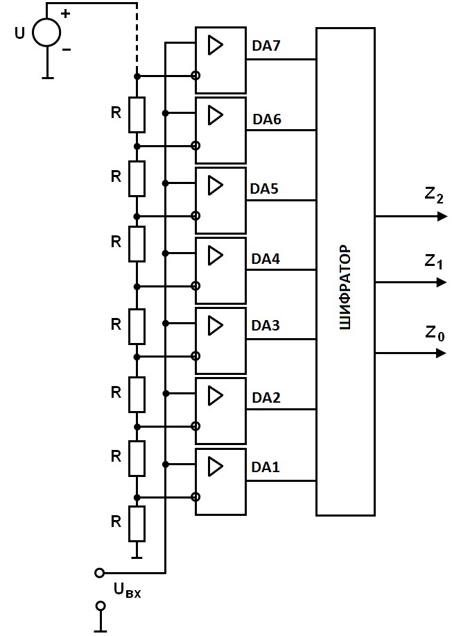
The diagram of a parallel analog-to-digital converter is shown in the figure. Parallel ADCs are the fastest analog-to-digital converters.
The number of electronic comparison devices (the total number of DA comparators) corresponds to the capacity of the ADC: three comparators are enough for two bits, seven for three, 15 for four, etc. The resistor voltage divider is designed to set a range of constant reference voltages.
The input voltage (the value of this input voltage is measured here) is simultaneously applied to the inputs of all comparators and compared to all reference voltages of those that this resistive divider allows to obtain.
Those comparators whose non-inverting inputs are fed with a voltage greater than the reference (applied by the divider to the inverting input) will give a logic one at the output, the rest (where the input voltage is less than the reference or equal to zero) will gave zero.
Then an encoder is connected, its task is to convert a combination of ones and zeros into a standard, adequately understood binary code.
ADC circuits for serial conversion are less fast than parallel converter circuits, but they have a simpler elementary design. It uses a comparator, AND logic, a clock, a counter, and a digital-to-analog converter.
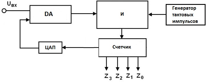
The figure shows a diagram of such an ADC. For example, while the measured voltage applied to the input of the comparator circuit is higher than the ramp signal of the second input (reference), the counter counts the pulses of the clock generator. It turns out that the measured voltage is proportional to the number of pulses counted.
There are also series-parallel ADCs, where the process of converting an analog signal to a digital signal is separated in space, so it turns out that the maximum trade-off speed is achieved with minimum complexity.