The main parameters of rectifier diodes
To correct low-frequency alternating currents, that is, to convert alternating current into direct or pulsating, they serve rectifier diodes, whose principle is based on the one-sided electrical conductivity of the p-n-junction. Diodes of this type are used in multipliers, rectifiers, detectors, etc.
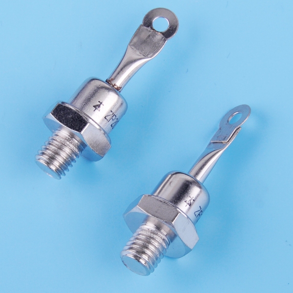
Flat or point junction rectifier diodes are manufactured, and the direct junction area can be from tenths of a square millimeter to units of square centimeters, depending on the current rating for a given half period rectified diode.
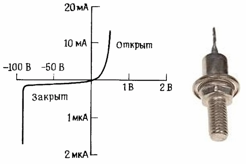
The current-voltage characteristic (CVC) of a semiconductor diode has a forward and reverse branch. The straight branch of the I — V characteristic practically shows the relationship between the current through the diode and the forward voltage drop in it, their interdependence.
The reverse branch of the I — V characteristic reflects the behavior of the diode when a voltage of reverse polarity is applied to it, where the current through the junction is very small and practically does not depend on the voltage applied to the diode until the limit is reached, where electrical breakdown of junction and the diode fails.
Maximum Diode Reverse Voltage — Vr
The first and main characteristic of a rectifier is the maximum allowable reverse voltage. This is the voltage, applying it to the diode in the opposite direction, it will still be possible to confidently say that the diode will withstand it and that this fact will not negatively affect the further operation of the diode. But if this voltage is exceeded, then there is no guarantee that the diode will not break.
This parameter is different for different diodes, it is in the range from tens of volts to several thousand volts. For example, for the popular rectifier 1n4007, the maximum DC reverse voltage is 1000V, and for the 1n4001, it is only 50V.
Average Diode Current — If
The diode rectifies current, so the next most important characteristic of a rectifier diode will be the average diode current—the average value of the rectified DC current flowing through the pn junction over the period. For rectifier diodes, this parameter can vary from hundreds of milliamps to hundreds of amperes.
For example, for a 2D204A rectifier, the maximum forward current is only 0.4A, and for an 80EBU04 - as much as 80A. If the average current turns out to be greater than the value indicated in the documentation for a long time, then there is no guarantee that the diode will survive.
Maximum Diode Pulse Current — Ifsm (single pulse) and Ifrm (repetitive pulses)
The maximum pulse current of a diode is the peak current value that a given rectifier can withstand only for a certain time, which is indicated in the documentation along with this parameter. For example, a 10A10 diode is able to withstand a single current pulse of 600A with a duration of 8.3 ms.
As for the repetitive pulses, their current should be such that the average current is within the permissible range. For example, the 80EBU04 diode will withstand repetitive square pulses with a frequency of 20 kHz even if their maximum current is 160A, but the average current should remain no more than 80A.
Average diode reverse current — Ir (leakage current)
The diode's average reverse current indicates the period average current through the junction in the reverse direction. Usually this value is less than a microamp, with a maximum of milliamps. For 1n4007, for example, the average reverse current does not exceed 5μA at a junction temperature of + 25 ° C and does not exceed 50 μA at a junction temperature of + 100 ° C.
Average diode forward voltage — Vf (junction voltage drop)
Average diode voltage at a given average current. This is the voltage that is applied directly to the p-n junction of the diode when a direct current of the value specified in the documentation passes through it. Usually no more than fractions, maximum — units of volts.
For example, the documentation for the EM516 diode gives a forward voltage of 1.2V for a current of 10A and 1.0V for a current of 2A. As you can see, the resistance of the diode is non-linear.
Diode differential resistance
The diode's differential resistance expresses the ratio of the voltage rise across the diode's pn-junction to the small current rise across the junction that caused that rise.Typically from fractions of an ohm to tens of ohms. It can be calculated from voltage drop versus forward current plots.
For example, for an 80EBU04 diode, an increase in current of 1A (from 1 to 2A) gives an increase of 0.08 V in the voltage drop across the junction. Therefore, the differential resistance of the diode in this range of currents is 0.08 / 1 = 0.08 Ohm.
Average power dissipation of a Pd diode
The average power dissipated by the diode is the average power dissipated by the body of the diode over the period when current flows through it in forward and reverse directions. This value depends on the design of the diode housing and can vary from hundreds of milliwatts to tens of watts.
For example, for the KD203A diode, the average power dissipated by the case is 20 W, this diode can even be installed, if necessary, on a heat sink to remove heat.