An additional pull-up resistor as a voltage divider
Figure 1 demonstrates the possibility of using a pull-up resistor as a voltage divider to obtain different output voltage levels. Output 3 of the circuit is connected to the body. The voltage divider current flows from top to bottom, making output 4 negative with respect to ground and outputs 2 and 1 positive.
Such a power supply is typical for electronic circuits containing bipolar transistors with the opposite type of conduction (n-R-n and p-n-p types), since the collector voltages of these transistors are positive and negative, respectively.
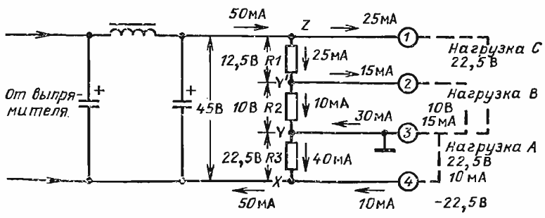
Rice. 1. Voltage divider in resistors
At node Z, the current that comes from the rectifier through the filter and the value of which is equal to 50 mA is divided into two equal components. One of these flows through the load C connected to ground, and the second through the resistor R1, creating a voltage drop of 12.5 V across it.
At the node marked with the letter Y ' 25 mA current flowing through resistor R1 is again branched into two circuits: 10 mA flows through resistor R2, creating a 10V positive voltage on it, and 16 mA through load B connected in parallel with resistor R2 .
It is clear that the voltage values across the load B and the resistor R2 are the same. It is also obvious that the resistance of the resistor R2 is 1.5 times the total resistance of the load B. If so, determine the value of the resistance of the resistor using the formula R = U / I Connecting current and voltage.
It should be noted that load C is connected in parallel with two series-connected resistors R1 and R2, therefore the voltage on it is positive relative to the case (output 3), is equal to the sum of the voltages on the indicated resistors and is 22.5 V.
At output 3, four currents are algebraically summed: the currents of loads A, B and C, as well as the current flowing in the wire connecting output 3 to the Y node of the voltage divider.
Load currents B and C have the same direction and flow into pin 3, and the two remaining currents have opposite direction, that is, they flow from pin 3. Assuming that the load current A is 10 mA, then to node Y through the connecting wire from pin 3 flows a current of 30 mA.
This current, added to the current of resistor R2, forms a current of 40 mA flowing through resistor R3 and creating a voltage equal to 22.5 V, which is of course equal to the voltage across load A. Summing up at node X, the currents of resistor R3 and loads A provide 50 mA of current flowing to the second output of the rectifier, which satisfies Kirchhoff's first law.