PFC power factor correction
The power factor and the harmonic factor of the mains frequency are important indicators of power quality, especially for the electronic equipment that is powered by this power.
It is desirable for the AC supplier that Power factor of consumers was close to unity, and for electronic devices it is important that harmonic distortions be as low as possible. Under such conditions, the electronic components of the devices will live longer, and the load will work more comfortably.
In fact, there is a problem, which is that the conventional linear power source is unable to provide the electronic equipment with electricity of suitable quality and even high efficiency. As a result, we have to accept the fact that the efficiency of the power supply unit of 80% with a power factor tending to 0.7 is considered the norm.
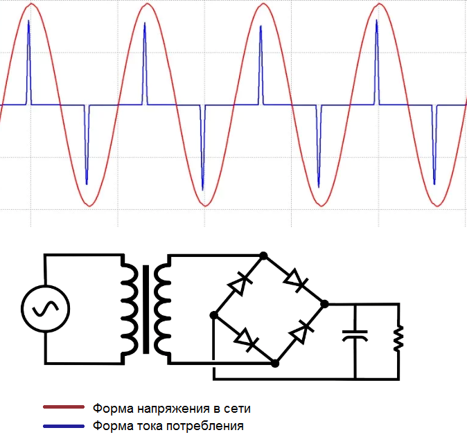
And the reason for this problem lies in the fact that at the entrance conventional switching power supply there is a diode bridge with a filter capacitor, and regardless of whether the rectified current consumer is even a linear load, the current supplied from the network to the diode bridge will still have bursts, pronounced isolated peaks, between which there are gaps with zero current consumption from the network.
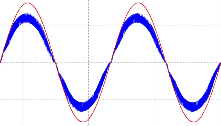
This happens because the filter capacitor charges and discharges unevenly, resulting in a reduction in power factor—actually, power from the grid is consumed in short pulses—one current pulse for every half of the grid's sine wave period.
In a circuit fed by such a filter capacitor, this phenomenon generates high harmonic distortion. And the power factor of a load fed by such a simple rectifier with a capacitor, as a rule, will not exceed 0.3.
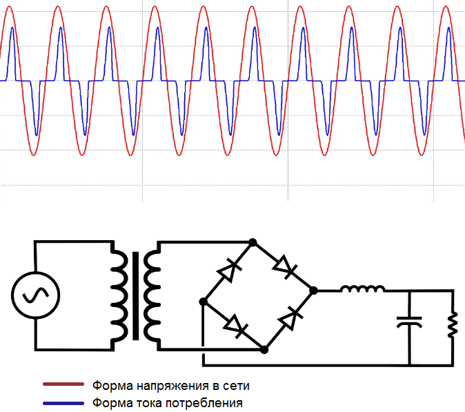
There is a simple "passive" way to slightly smooth out the sharp current peaks, slightly increase the power factor and slightly decrease this way accordions… The method consists of adding an inductor between the diode bridge and the filter capacitor. This will slightly round the peaks to a sinusoidal shape.
In this case, however, the power factor will still be far from unity (about 0.7), since the shape of the current consumed is again not sinusoidal at all. And when many such plan of users with different capacities are connected to the grid, it becomes a serious problem for the power generating party.
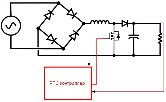
The best way to improve power factor and reduce line frequency harmonics is to use relatively simple active power factor correction (PFC) schemes based on pulse-boost converters in switching power supplies.Here, not only an inductor is added to the input rectifier circuit, but also a field-effect transistor with a driver and controller, as well as a diode.
During active power factor correction (active PFC), the FET rapidly switches between the two states.
The first state — when the switch is closed, the choke receives power from the rectifier, stores energy in the magnetic field, while the diode is reverse biased, and the load is powered only by the filter capacitor.
The second state is when the transistor is open, during this part of the cycle the diode goes into the conducting state, and the choke now transfers energy to the load and charges the capacitor. Such switching occurs with a frequency of several tens of kilohertz for each half-wave of the mains sine wave.
The key control circuit adjusts the duration of the time intervals—how long the choke is connected to the grid and how long it energizes the capacitor so that the voltage across the capacitor is maintained at a constant level, such as the average choke current. This circuit increases the power factor of the supply to 0.98.
Competent switching management is necessary so that the current consumption is in phase with the alternating voltage of the network. For this purpose, the controller generates a PWM signal to control the gate of the FET, so that at the peak of the sine wave, the choke receives energy for a shorter time than at a voltage close to zero (longer).
The PFC controller has an output voltage feedback loop (which is compared to a reference and held constant via PWM), as well as an input voltage and inductor current sensor to accurately monitor the average inductor current in real time to ensure that the load has the maximum power factor.