FET gate protection
It would not be an exaggeration to call the isolated gate of an FET a rather sensitive part of it that needs individual protection. Cracking the lid is a fairly simple phenomenon. This can happen for several reasons: electrostatic pickup, parasitic oscillations in the control circuits and, of course, the Miller effect, when an overvoltage arising on the collector through capacitive coupling has a detrimental effect on the gate.

One way or another, these causes can be prevented by reliably ensuring compliance with the rules of transistor operation: do not exceed the maximum permissible gate-source voltage, ensure reliable and timely locking to avoid through currents, make the connecting wires of control circuits as short as possible (to achieve the lowest parasitic inductance), as well as for maximum protection of the control circuits themselves from interference. Under such conditions, none of the listed reasons simply can manifest itself and harm the key.
So, as for the gate itself, it is useful to use special schemes to protect it, especially if the connection of the driver to the gate and the source cannot be done closely due to the design features of the device being developed. In any case, when it comes to protecting the hood, the choice falls on one of four main schemes, each of which is ideal for certain conditions, which will be discussed below.
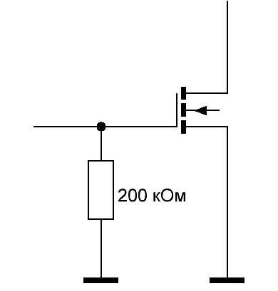
A single resistor

Basic gate protection against static electricity can be provided by a single 200 kΩ resistor when installed side by side between the drain and the source of the transistor… To some extent, such a resistor is able to prevent the gate from charging, if for some reason the impedance of the driver circuits plays a negative role.
A single-resistor solution is ideal for protecting a transistor in a low-frequency device where it directly switches a purely resistive load, that is, when no inductor inductance or transformer winding is included in the collector circuit, but a load such as an incandescent lamp or LED, when the effect Miller's is not out of the question.
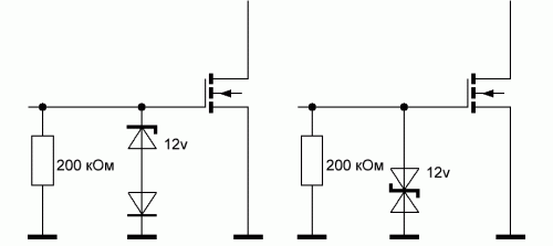
Zener Diode or Schottky Suppressor (TVS)
A classic of the genre for the protection of transistor gates in mains switching converters - a zener diode in a pair with Schottky diode or oppressive. This measure will protect the gate-source circuit from the destructive influence of the Miller effect.
Depending on the mode of operation of the switch, a 13-volt zener diode (with a 12-volt driver voltage) or a suppressor with a similar typical operating voltage is selected. If you want, you can also add a 200 kΩ resistor here.
The purpose of the suppressor is to quickly absorb impulse noise. Therefore, if it is immediately known that the operating mode of the switch will be difficult, accordingly, the protection conditions will require the limiter to dissipate high impulse powers and a very fast response — in this case, it is better to choose a suppressor. For softer modes, a zener diode with a Schottky diode is suitable.
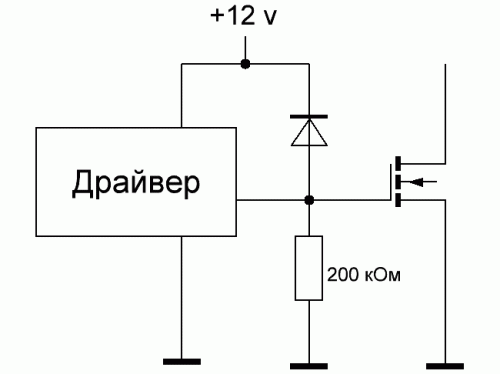
Schottky diode on the driver power circuit
When the low-voltage driver is installed on the board near the controlled transistor, a single Schottky diode can be used for protection, connected between the gate of the transistor and the low-voltage supply circuit of the driver. And even if for some reason the gate voltage is exceeded (it becomes higher than the driver supply voltage plus the voltage drop across the Schottky diode), excess charge will simply enter the driver supply circuit.
Professional developers of power electronics recommend using this solution only if the distance from the key to the driver does not exceed 5 cm. The static protection resistor that was mentioned above does not hurt here either.


