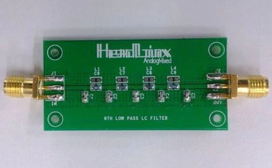
General principle of construction of passive LC-filters (LPF and HPF)
When it is necessary to suppress alternating currents with a certain frequency spectrum in the circuit, but at the same time effectively pass currents with frequencies above or below this spectrum, a passive LC filter on reactive elements can be useful - a low-pass filter on a low-pass filter (if necessary effective passage of oscillations with a frequency below the set) or high-pass filter HPF (if necessary, effective passage of oscillations with a frequency higher than the set).
The principle of construction of these filters is based on the properties of inductors and capacitors to behave differently in AC circuits.
It is well known that inductive resistance coils is directly proportional to the frequency of the current flowing through it, therefore, the higher the frequency of the current flowing through the coil, the greater reactivity it displays this current, that is, it slows down alternating currents at higher frequencies more and passes currents at lower frequencies more easily.
Condenser — on the contrary, the higher the frequency of the current, the more easily this alternating current penetrates through it, and the lower the frequency of the current, the greater the obstacle to the current is this capacitor. Schematically, the low-pass and high-pass filters are L-shaped, T-shaped and U-shaped (multi-junction).
L-shaped LC filter
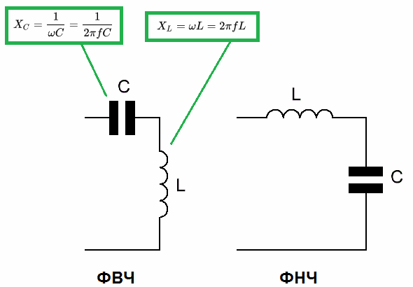
The L-shaped filter is an elementary electronic filter consisting of a coil of inductance L and a capacitor of capacitance C. The frequency response of such a circuit depends on the order of connection of two elements (L and C) relative to the point where a filtered signal is applied and to the values of L and C ...
In practice, the values of L and C are selected so that their reactance in the operating frequency range is approximately 100 times smaller than the load resistance, in order to significantly reduce the maneuvering effect of the latter on the frequency response of a filter.
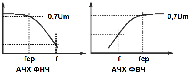
The frequency at which the amplitude of the signal applied to the filter drops to 0.7 of its original value is called the cutoff frequency. An ideal filter has a steep vertical deflection.
So, depending on the sequence of connection of the inductor L and the capacitor C with respect to the signal source and the neutral bus, you get a high-pass filter - HPF or a low-pass filter - LPF.
In fact, these circuits are voltage dividers, and reactive elements are installed in the arms of the divider, whose resistance to alternating current depends on the frequency.
Here you can easily calculate the voltage drop in each of the filter elements, taking into account that at the cutoff frequency, the voltage drop at the filter output should be equal to 0.7 of the input voltage amplitude.This means that the ratio between the reagents should be 0.3 / 0.7 - based on this ratio, the separator that makes up the filter is calculated.
When the load circuit is open, in low-pass filters, when the frequency of the input signal exceeds the resonant frequency of the LC-circuit of the filter, the amplitude of the output begins to decrease sharply. In high-pass filters, when the frequency of the input signal falls below the resonant frequency of the LC circuit of the filter, the amplitude of the output also begins to fall. In practice, LC filters are not used as such without load.
T-shaped LC filter
To weaken the shunting effect of the filter on the sensitive circuits connected behind it, T-shaped filters are used. Here, an additional reactive element is added to the L-connection, on the side of its output.
The capacity or inductance practically calculated for the L-shaped LC filter is replaced by the series connection of a pair of identical elements so that their total resistance is equal to the calculated element that is replaced by this pair (they put two halves of inductances or two capacitors , which are twice as large in capacity).
U-shaped LC filter
By adding an additional element to the L-shaped connection, but not at the back, but at the front, a U-shaped filter is obtained. This circuit biases the input source more. Here the element added is half the calculated capacitance for the L-connection (which is simply divided into two capacitive elements) or twice the inductance value now obtained by connecting two coils in parallel.
The more connections there are in the filter, the more accurate the filtering will be.As a result, the highest amplitude of the load will have the frequency that for this filter will be closest to its resonance frequency (the condition is that the inductive component of the connection is equal to this frequency of its capacitive component), the rest of the spectrum will be suppressed.
The use of multi-level filters makes it possible to very precisely separate the signal of the desired frequency from the noisy signal. Even if the amplitude at the cut-off frequency is relatively small, the rest of the range will be suppressed by the general effect of the filter taps.