Switching Power Supplies — General Principles, Advantages and Disadvantages
Today, it is already difficult to find an iron transformer in any household appliance or power supply. In the 1990s, they began to rapidly fade into the past, giving way to switching converters or switching power supplies (abbreviated as SMPS).
Switching power supplies surpass transformers in terms of size, quality of the resulting DC voltage, have wide options for regulating the output voltage and current, and are traditionally equipped with output overload protection. And although switching power supplies are believed to be the main providers of interference in the household network, their widespread use cannot be reversed.
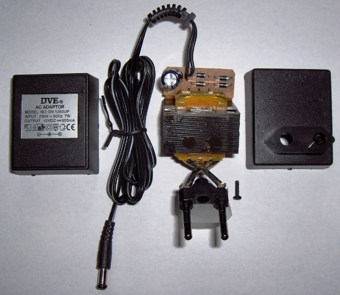
Transformer supply:
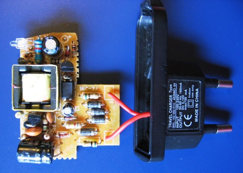
Switch current:
Switching power supplies owe their ubiquity to semiconductor switches— field effect transistors and Diode Schottky… It is the field-effect transistor, working together with a choke or transformer, that is the heart of every modern switching power supply: in inverters, welding machines, uninterruptible power supplies, built-in power supplies for TVs, monitors, etc. — nowadays only pulse conversion circuits are used almost everywhere voltage.
The general principle of operation of a pulse converter is based on the law of electromagnetic induction and is similar in this with each transformer… The only difference is that an alternating voltage with a mains frequency of 50 Hz is applied directly to the primary winding of a conventional mains transformer and converted directly (then, if necessary, rectified), and in a switching power supply, the mains voltage is first rectified and converted to DC and then converted to a pulse to be further increased or decreased using a special high frequency (compared to 50 hertz mains) circuit.
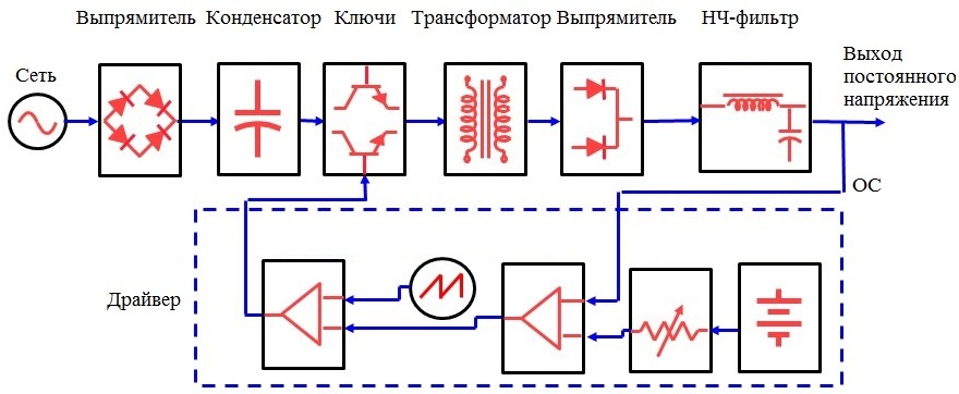
A switching power supply circuit includes several main components: a mains rectifier, a switch (or switches), a transformer (or choke), an output rectifier, a control unit, and a stabilization and protection unit. The rectifier, switch and transformer (choke) form the basis of the power part of the SMPS circuit, while the electronic blocks (including the PWM controller) belong to the so-called driver.
So, the mains voltage is fed through the rectifier to the capacitor of the mains filter, where in this way a constant voltage is obtained, the maximum of which is from 305 to 340 volts, depending on the current average value of the mains voltage ( from 215 to 240 volts) .
The rectified voltage is applied to the primary winding of the transformer (choke) in the form of pulses, the repetition frequency of which is usually determined by the key control circuit, and the duration of which is determined by the average current of the supplied load.
A switch with a frequency of several tens to several hundred kilohertz connects and disconnects the primary winding of the transformer or choke to the filter capacitor, thereby reversing the magnetization of the transformer or choke core.
The difference between a transformer and a choke: in a choke, the phases of storing energy from the source to the core and transferring energy from the core through the winding to the load are separated in time, while in a transformer this happens simultaneously.
The choke is used in converters without galvanic isolation of topologies: boost - boost, step - down, as well as in converters with galvanic isolation of reverse topology. The transformer is used in converters with galvanic isolation of the following topologies: bridge-full-bridge, half-bridge-half-bridge, push-pull-push-pull, forward-forward.
The switch can be a single one (buck-up converter, forward converter, boost or buck converter without galvanic isolation) or the power section can include several switches (half-bridge, bridge, push).
The control circuit of the switch(s) receives from the output of the source a feedback signal for voltage or for voltage and current of the load, in accordance with the value of this signal, the width (duty cycle) of the pulse, which controls the duration of the conductive state of the switch is adjusted automatically.
The output is arranged as follows. From the secondary winding of the transformer or inductor, or from the single winding of the inductor (if we are talking about a converter without galvanic isolation), through the Schottky diodes of a full-wave rectifier, a pulsed voltage is supplied to the filter capacitor.
There is also a voltage divider from which the voltage feedback signal is received, and a current sensor may also be present. The load is connected to the filter capacitor through an additional output low-pass filter or directly.