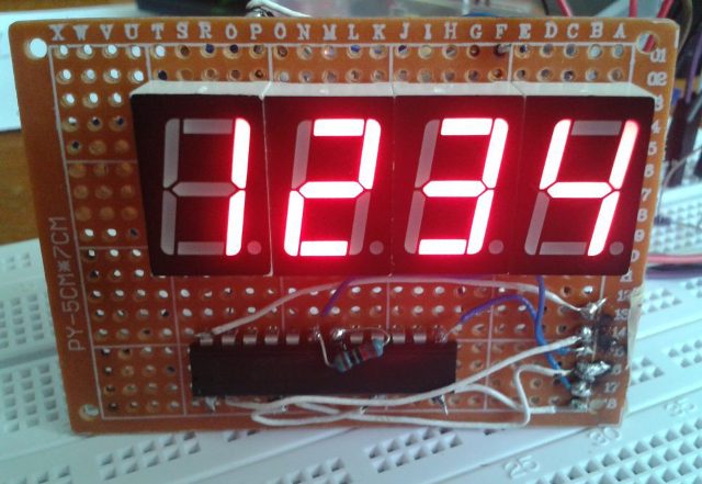
LED indicators - types and applications
An LED indicator is an electronic device that contains multiple LEDs. Each LED indicator is part of a whole, so several indicator LEDs, when turned on in a certain combination, can form a certain symbol or complex image.
Indicator LEDs can be single-color or multi-color. Typically, single-color LEDs contain red, yellow, green, or blue LEDs, while multi-color LEDs contain RGB LEDs.
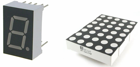
The LEDs that make up the indicator can be of different shapes: round, square, rectangular, SMD LEDs, etc.
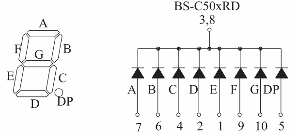
Single color segment LEDs show the number. An example of the simplest indicator of this type is bs-c506rd or bs-a506rd - a seven-segment red indicator that forms a digit with a dot. Inside the housing of this indicator there are 8 LEDs, the cathodes (bs-C506rd) or anodes (bs-A506rd) of which are combined to one common terminal.
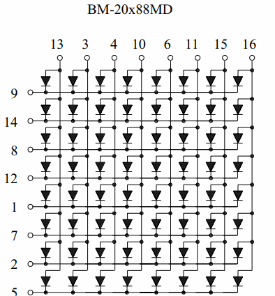
More complex LED indicators are matrix LEDs such as the BM-20288MD or BM-20288ND.Specifically, these models contain 64 LEDs, the cathodes of which (BM-20288MD) are combined to form 8 separate rows and the anodes - 8 separate columns. Practically, on the basis of such an indicator, it is possible to display any symbol (letter, number, sign or even a small picture) with a resolution of 8×8 pixels.
LED indicator control circuit
The switch circuit of the indicator contains separate circuits for powering each LED in the indicator. How these circuits are constructed depends on the purpose of the indicator housing pins, which can be easily ascertained by looking at the datasheet.
The indicator LEDs are often powered directly from the terminals of specialized digital TTL chips, whose own nominal supply voltage is usually 5 volts, and the designer only has to choose the value of the current limiting resistors.
The voltage drop characteristic of LEDs does not exceed 3 volts, and the operating current (within a few mA) is much less than what almost any modern microcircuit can withstand.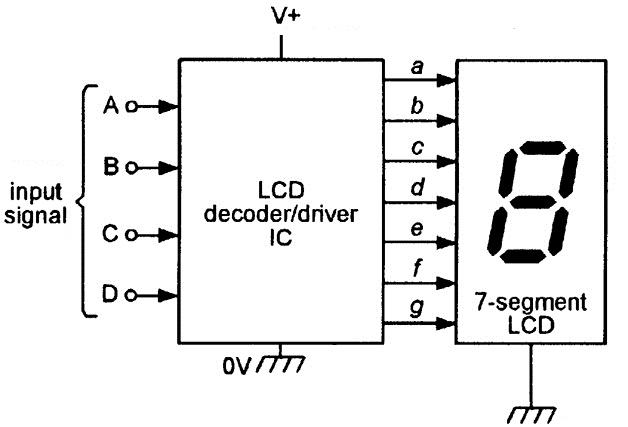
However, before powering the indicator directly from the microcircuit, its parameters must always be precisely matched to the future load (with the parameters of the selected indicator). If the supply voltage of the microcircuit is less than required, then you will have to use the open collector terminals to which the voltage required by the indicator LEDs (higher than that of the microcircuit) is supplied. In extreme cases, you will need to add external transistors.
Principle of dynamic indication
If the display device contains in its design a large number of LED indicators of the same type, then it is not always convenient to introduce too many wires from too many microcircuits. To prevent the accumulation of chips and wires, you can take advantage of the perception inertia of the human eye.
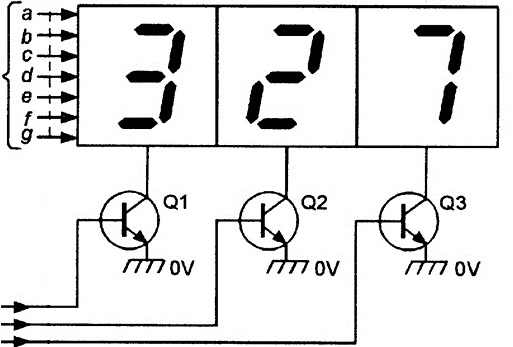
Let each of the indicators turn on and off one after the other with such a frequency that the human eye does not notice this flicker. At a frequency of 50 Hz to a person, it will appear that all indicators are constantly on and do not go out for a moment.
The circuit will turn out to be much simpler: only one board forming the symbols is needed, all the indicators can be connected to it in parallel, as if it were only one indicator; while power will have to be applied to the indicators sequentially and cyclically. When the first symbol is formed — power is applied to the first indicator, when the second symbol is formed — the second indicator is on, and so on.