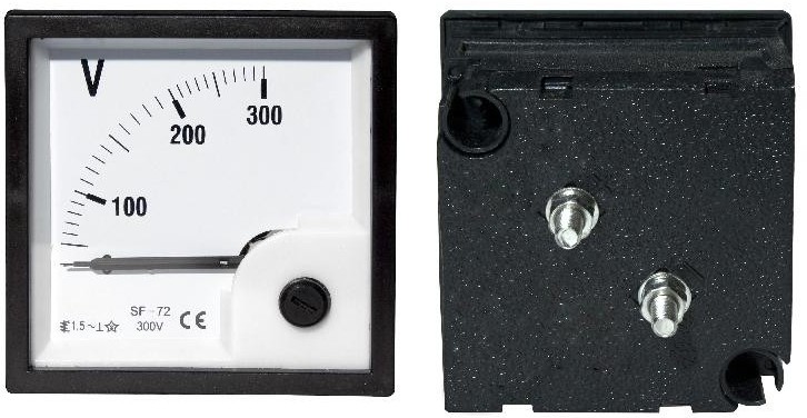
Measuring voltage with a voltmeter
A device called a voltmeter is used to measure AC or DC voltage in AC and DC circuits. Since there is a voltage between different points of the circuit or at the poles of the voltage source, the voltmeter is always connected in parallel with the section of the circuit under test or in parallel with the terminals of the voltage source.
Of course, you can turn on the voltmeter and in series, in an open circuit, but then the voltage of the source will be measured, and not of the section of the circuit, since the circuit will be open and the voltmeter itself has a very large internal resistance.
Voltmeters are produced both as separate electrical measuring devices and in the format of one of the functions of multimeters. In the input circuit of a modern voltmeter there is usually a megohm -resistor connected in series with an electronic measuring circuit.
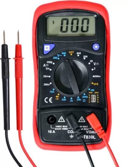
A voltmeter, as a separate measuring device or as one of the functions of a multimeter, has several voltage measurement ranges. The range is selected using a switch located on the front panel of the device.
Usually one of the following values can be selected on the multimeter (maximum value for the range): 200mV, 2000mV (2V), 20V, 200V, 600V, etc. Typically, multimeters have the ability to measure AC and DC voltage. The type of voltage is also selected on the scale of the switch.
For measuring current and voltage, multimeters have two separate test leads: one for measuring voltage and one for measuring current. The third is the common wire, which remains in place regardless of what is being measured, current or voltage.
Connect the test leads to the appropriate jacks on a multimeter or voltmeter. Turn on the device and put it in voltage measurement mode by selecting the voltage type and range using the switch. If the range is unknown, then it is worth starting with the largest available value on the switch scale, then you can reduce it.
Connection diagram of a voltmeter for measuring the voltage drop on a light bulb:
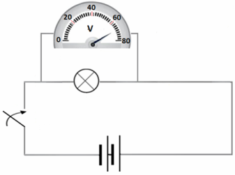
Connect the test leads (be careful!) so that the device is connected to the correct points of the circuit between which you want to measure the voltage. After a few seconds, the device will show the actual value of the measured voltage on the display.
If the range is 600V or more, the measured voltage value will be displayed in volts. If the range is, for example, 2000mV or 200mV (the order of the voltage values, but in general the scale values may differ from these), then the display will show readings in millivolts.
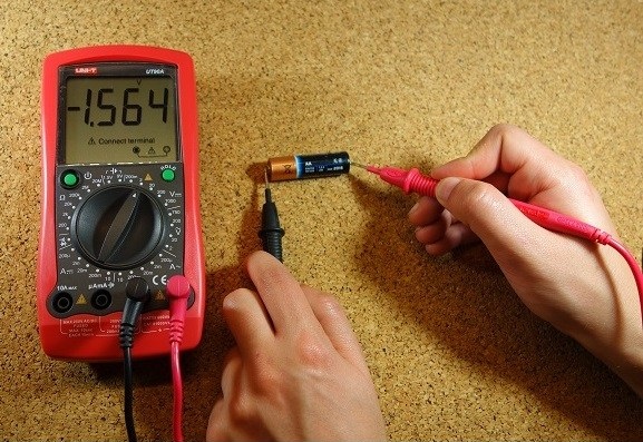
If a DC voltage is being measured, depending on the polarity and correct position of the probes, the display may show a number with a minus sign in front of it.
This means that the red and black probes must be reversed, as the red probe is for the positive pole and the black probe for the negative pole with respect to the DC voltage source that is installed in the circuit under test.
A voltmeter (or multimeter) that is not designed to measure high-frequency voltages or voltages higher than the maximum on its scale will easily fail if you try to measure high-frequency or higher voltages with it. The documentation for the device always indicates the type of current and the maximum permissible voltage parameters that can be measured.