The device and principle of operation of the transformer
To convert an electrical voltage of one magnitude to an electrical voltage of another magnitude, that is, to convert electrical energy, use electrical transformers.
A transformer can only convert alternating current to alternating current, therefore, to obtain direct current, the alternating current from the transformer is rectified if necessary. For this purpose they serve rectifiers.
In one way or another, every transformer (be it a voltage transformer, a current transformer or a pulse transformer) works due to the phenomenon of electromagnetic induction, which manifests itself in all its glory precisely with alternating or pulse current.
Transformer device
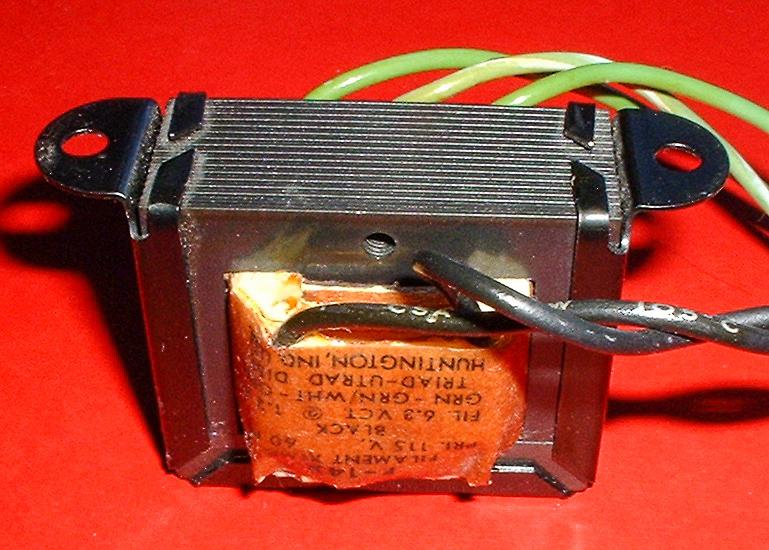
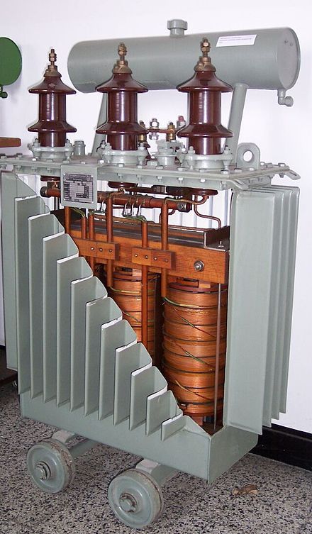
In its simplest form, a single-phase transformer consists of only three main parts: a ferromagnetic core (magnetic circuit), as well as primary and secondary windings. In principle, a transformer can have more than two windings, but at least two of them. In some cases, the function of the secondary winding can be performed by part of the turns of the primary winding (see Fig. types of transformers), but such solutions are quite rare compared to the usual ones.
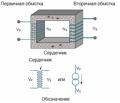
The main part of the transformer is a ferromagnetic core. When the transformer is operating, the changing magnetic field is within the ferromagnetic core. The source of the changing magnetic field in the transformer is the alternating current of the primary winding.
Transformer secondary winding voltage
It is known that every electric current is accompanied by a magnetic field; accordingly, an alternating current is accompanied by an alternating (changing in magnitude and direction) magnetic field.
Thus, by supplying alternating current to the primary winding of the transformer, we get a changing magnetic field of the primary winding current. And so the magnetic field is mainly concentrated in the core of the transformer, this core is made of a material with high magnetic permeability, thousands of times greater than that of air, so the main part of the magnetic flux of the primary winding will be closed exactly inside the core, not through air.
Thus, the alternating magnetic field of the primary winding is concentrated in the volume of the transformer core, which is made of transformer steel, ferrite or other suitable material, depending on the operating frequency and purpose of a particular transformer.
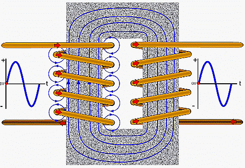
The secondary winding of the transformer is located on a common core with its primary winding. Therefore, the alternating magnetic field of the primary winding also penetrates the turns of the secondary winding.
A phenomenon of electromagnetic induction it simply lies in the fact that a time-varying magnetic field causes a changing electric field in the space around it. And since there is a second coil wire in this space around the changing magnetic field, the induced alternating electric field acts on the charge carriers inside this wire.
This electric field action causes an EMF with each turn of the secondary coil. As a result, an alternating electric voltage appears between the terminals of the secondary winding. When the secondary winding of the connected transformer is not loaded, the transformer is empty.
Operation of the transformer under load
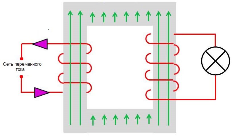
If a certain load is connected to the secondary winding of an operating transformer, a current arises through the load in the entire secondary circuit of the transformer.
This current generates its own magnetic field, which, according to Lenz's law, has such a direction that it opposes the "cause that causes it." This means that the magnetic field of the current of the secondary winding at any instant of time tends to reduce the increasing magnetic field of the primary winding or tends to support the magnetic field of the primary winding when it decreases, it always points to the magnetic field of the primary coil.
Thus, when the secondary winding of the transformer is loaded, a back EMF occurs in its primary winding, forcing the primary winding of the transformer to draw more current from the supply network.
Transformation factor
The turns ratio of the primary N1 and secondary N2 windings of a transformer determines the ratio between its input U1 and output U2 voltages and input I1 and output I2 currents when the transformer is operating under load. This ratio is called transformation ratio of the transformer:
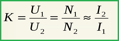
The transformation factor is greater than one if the transformer is stepped down and less than one if the transformer is stepped up.
Voltage transformer
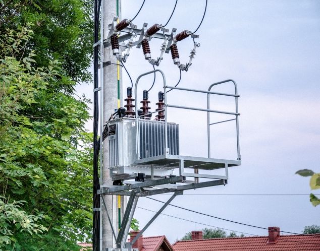
A voltage transformer is a type of step-down transformer designed to galvanically isolate high-voltage circuits from low-voltage circuits.
Usually, when it comes to high voltage, they mean 6 kilovolts or more (on the primary winding of the voltage transformer), and low voltage means values on the order of 100 volts (on the secondary winding).
Such a transformer is used, as a rule, for measurement purposes… It steps down, for example, the high voltage of the power line to a convenient low voltage for measurement, while also being able to galvanically isolate the measurement, protection, control circuits from the high voltage circuit. These type of transformers usually operate in idle mode.
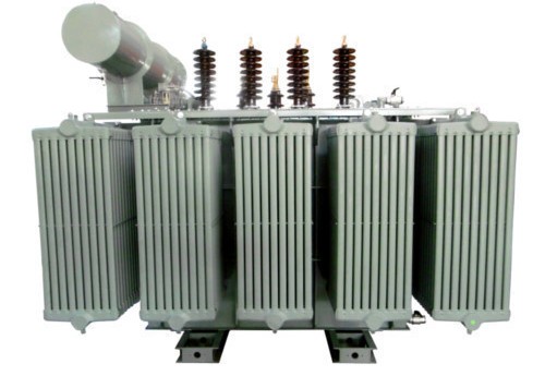
Basically anything can be called a voltage transformer power transformerused to convert electrical energy.
Current transformer
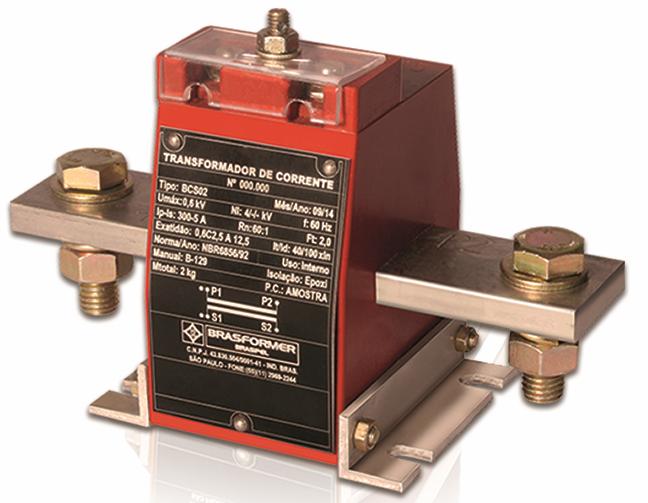
In a current transformer, the primary winding, which usually consists of only one turn, is connected in series with the current source circuit. This turn may be a section of the circuit wire where the current needs to be measured.
The wire is simply passed through the window of the transformer core and becomes this single turn—the turn of the primary winding. Its secondary winding, which has many turns, is connected to a measuring device that has low internal resistance.
Transformers of this type are used to measure alternating current values in power circuits. Here the current and voltage of the secondary winding are proportional to the measured current of the primary winding (current circuit).
Current transformers are widely used in relay protection devices for power systems, therefore they have high accuracy. They make measurements safe, as they galvanically reliably isolate the measuring circuit from the primary circuit (usually high voltage — tens and hundreds of kilovolts).
Pulse transformer
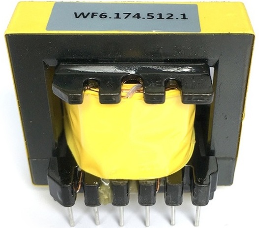
This transformer is designed to convert a pulse form of current (voltage). Short pulses, usually rectangular, applied to its primary winding make the transformer work practically in transient conditions.
Such transformers are used in pulse voltage converters and other pulse devices, as well as in differentiating transformers.
The use of pulse transformers allows to reduce the weight and cost of the devices in which they are used, simply because of the increased conversion frequency (tens and hundreds of kilohertz) compared to network transformers operating at a frequency of 50-60 Hz. Rectangular pulses, whose rise time is much less than the pulse duration itself, are usually transformed with low distortion.