Full wave midpoint rectifier
If we talk about single-phase diode rectifiers in general, then the mid-point full-wave rectifier allows you to get lower losses on the diodes themselves, since there are only two diodes.
In addition, usually such rectifiers are used in low-voltage devices where the current through the diodes is essential. Therefore, in this aspect, a full-wave midpoint circuit is more advantageous, since the energy losses in the diodes are proportional of the square of the average value of the current flowing through them.
And when you consider availability and quality Diode Schottky (low forward voltage drop) that are widely available on the market today, the choice in favor of a midpoint circuit is obvious.
And if we are talking about transformer-pulse converters with a push-pull transformer (bridge, half-bridge, push-pull) operating at frequencies much higher than the usual network frequency, then only the rectifier circuit with a middle point remains and no other.
However, in this article we will focus on the calculation of the rectifier in relation to a low line frequency of 50 Hz, where the rectified current is sinusoidal.
First of all, it should be noted that in the rectifier, which is built according to this scheme, it obliges us to have a transformer with two identical secondary windings or with one secondary winding, but with an output in the middle (which is essentially the same).
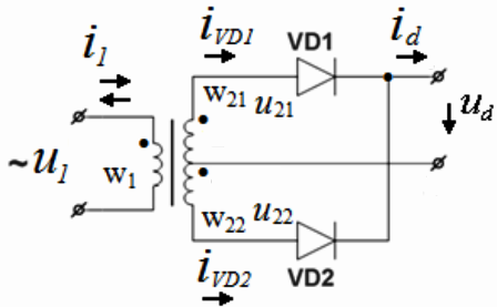
The voltage obtained in series from the half-windings of such a transformer is actually two-phase with respect to the midpoint, which acts as a zero point during rectification, since two EMFs equal in magnitude but opposite in direction are formed here. That is, the voltages at the end terminals of the secondary winding of the transformer, which arise at any moment of its operation, are phase-shifted by 180 degrees.
The opposite terminals of the windings w21 and w22 are connected to the anodes of the diodes VD1 and VD2, while the voltages u21 and u22 applied to the diodes are in antiphase.
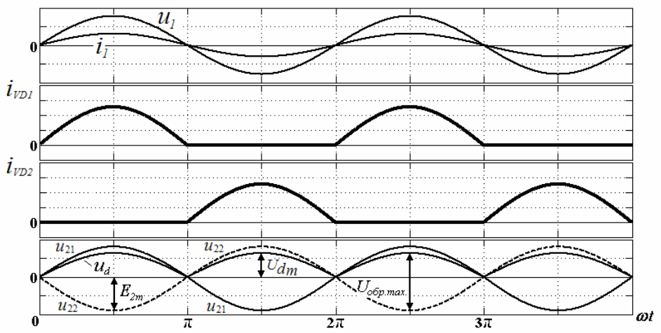
Therefore, the diodes conduct current in turn - each during its half-cycle of the supply voltage: during one half-cycle, the anode of the diode VD1 has a positive potential and the current i21 flows through it, through the load and through the coil (semi-coil) w21, while the diode VD2 is in the reverse bias condition, it is locked, hence no current flows through half-coil w22.
During the next half-cycle, the anode of the VD2 diode has a positive potential and the current i22 flows through it, through the load and through the coil (semi-coil) w22, while the diode VD1 is in the reverse biased state, it is locked, therefore the current does not flow through the half-coil w21.
The result achieved is that the current flows through the load always in the same direction, that is, the current is rectified. And each of the halves of the secondary winding of the transformer turns out to be loaded for only half a period of two. For a transformer, this means that magnetization never occurs in its magnetic circuit because the magnetomotive forces of the DC components of the winding currents are directed oppositely.
Let us denote the effective voltage between the midpoint and the far terminal of one of the half-windings as U2. Then the average rectified voltage Ud between the middle point of the secondary winding and the connection point of the cathodes of the diodes is obtained. In this case, the average value of the voltage in the load will be:
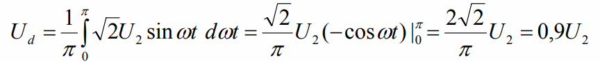
We see that the average value of the rectified voltage is related to the rms value in the same way that the average value of the current is related to the rms value of the current with an unrectified sinusoidal voltage.
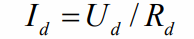
The average value of the load current is found by the formula (where Rd is the load resistance):
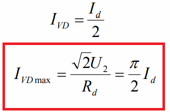
And since the current flows through the diodes in series, you can now find the average current of each diode and the amplitude of the current for each diode. When choosing a diode for such a rectifier, it is important to pay attention to the fact that the maximum allowable current of the diode is slightly higher than the value established according to this formula:
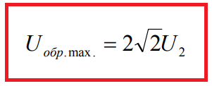
When designing a full-wave midpoint rectifier, it is also important to remember that the reverse voltage applied to a locked diode while the other diode is conducting reaches twice the amplitude of the half-coil voltage.Therefore, the maximum reverse voltage for the selected diode must always be greater than this value:
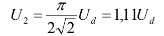
When the output (corrected) voltage Ud is specified, then the effective value of the voltage U2 of the secondary half-winding will be related to it as follows (compare with the first formula):
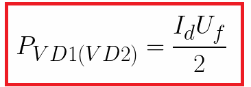
In addition, when designing a rectifier and setting the average output voltage Ud to be obtained under load, it is necessary to add to it the forward voltage drop across the diode Uf (it is given in the diode documentation). Multiplying half the average load current by the forward voltage drop across the diode gives us the amount of power that will inevitably have to be dissipated in each of the two diodes as heat:
When choosing diodes, it is important to take this into account, to assess the capabilities of the diode housing, whether it can dissipate so much power and not fail at the same time. If necessary, you will need to make additional thermal calculations regarding the selection of heatsinks to which these diodes will be attached.