Self induction and mutual induction
EMF of self-induction
A variable current always creates a variable magnetic field, which in turn always causes EMF... With each change of current in the coil (or in general in the wire), it itself induces an EMF of self-induction.
When an emf in a coil is induced by a change in its own magnetic flux, the magnitude of that emf depends on the rate of change of the current. The greater the rate of change of the current, the greater the EMF of the self-induction.
The magnitude of the emf of self-induction also depends on the number of turns of the coil, the density of their winding and the size of the coil. The larger the diameter of the coil, the number of its turns and the density of the winding, the greater the EMF of self-induction. This dependence of the EMF of self-induction on the rate of change of the current in the coil, the number of its turns and dimensions is of great importance in electrical engineering.
The direction of the emf of self-induction is determined by Lenz's law. The EMF of self-induction always has a direction in which it prevents a change in the current that caused it.
In other words, the reduction of the current in the coil leads to the appearance of an EMF of self-induction directed in the direction of the current, i.e. preventing its reduction. Conversely, as the current increases in the coil, an EMF of self-induction appears, directed against the current, that is, preventing its increase.
It should not be forgotten that if the current in the coil does not change, then no EMF of self-induction occurs. The phenomenon of self-induction is especially pronounced in a circuit containing a coil with an iron core, since iron significantly increases the magnetic flux of the coil and, accordingly, the magnitude of the EMF of the self-induction when it changes.
Inductance
So, we know that the magnitude of the self-induction EMF in the coil, in addition to the rate of change of the current in it, also depends on the size of the coil and the number of its turns.
Therefore, coils of different design at the same rate of change of current are capable of self-inducing emf of self-induction of different magnitude.
In order to distinguish coils from each other by their ability to induce EMF of self-induction in themselves, the concept of inductive coils, or coefficient of self-induction, was introduced.
The inductance of the coil is a quantity that characterizes the property of the coil to induce the EMF of self-induction by itself.
The inductance of a given coil is a constant value, independent of both the strength of the current passing through it and the rate of its change.
Henry - this is the inductance of such a coil (or wire) in which, when the current strength changes by 1 ampere in 1 second, an EMF of self-induction of 1 volt arises.
In practice, sometimes you need a coil (or coil) that has no inductance. In this case, the wire is wound on a coil, having previously folded it twice. This winding method is called bifilar.
EMF of mutual induction
We know that the EMF of induction in a coil can be caused not by moving the electromagnet in it, but by changing only the current in its coil. But what, in order to cause an EMF of induction in one coil due to a change in current in another, it is absolutely not necessary to put one of them in the other, but you can arrange them next to each other
And in this case, when the current in one coil changes, the resulting alternating magnetic flux will penetrate (cross) the turns of the other coil and cause EMF in it.
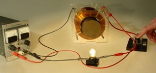
Mutual induction makes it possible to connect different electric circuits by means of a magnetic field. This connection is commonly called an inductive coupling.
The magnitude of the mutual induction emf depends primarily on the rate at which the current in the first coil is changing…. The faster the current changes in it, the greater the EMF of the mutual induction.
In addition, the magnitude of the mutual induction EMF depends on the magnitude of the inductance of the two coils and their relative position, as well as the magnetic permeability of the environment.
Therefore, Coils, which are different in their inductance and mutual arrangement and in different environments, are capable of inducing in each other, different in magnitude, mutual induction EMFs.
To be able to distinguish between different pairs of coils by their ability to mutually induce an EMF, the concept of mutual inductance or mutual induction coefficient.
Mutual inductance is denoted by the letter M. The unit for its measurement, like inductance, is the henry.
A henry is such a mutual inductance of two coils that a change in current in one coil of 1 amp for 1 second causes an emf of mutual induction equal to 1 volt in the other coil.
The magnitude of the mutual induction EMF is affected by the magnetic permeability of the environment. The greater the magnetic permeability of the medium through which the alternating magnetic flux connecting the coils is closed, the stronger the inductive coupling of the coils and the greater the EMF value of the mutual induction.
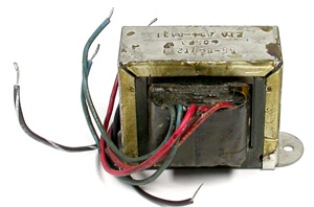
The work is based on the phenomenon of mutual induction in such an important electrical device as a transformer.
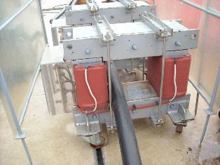
The principle of operation of the transformer
The principle of operation of the transformer is based on the phenomenon of electromagnetic induction and is as follows. Two coils are wound on the iron core, one of them is connected to a source of alternating current and the other to a current sink (resistance).
A coil connected to an AC source creates an alternating magnetic flux in the core, which induces an EMF in the other coil.
The coil connected to the AC source is called the primary and the coil to which the consumer is connected is called the secondary. But since the alternating magnetic flux simultaneously penetrates both coils, an alternating EMF is induced in each of them.
The magnitude of the EMF of each turn, like the EMF of the entire coil, depends on the magnitude of the magnetic flux penetrating the coil and the rate of its change.The rate of change of the magnetic flux depends only on the frequency of direct alternating current for a given current. The magnitude of the magnetic flux is also constant for this transformer. Therefore, in the considered transformer, the EMF in each winding depends only on the number of turns in it.
The ratio of primary to secondary voltage is equal to the ratio of the number of turns of the primary and secondary windings. This relationship is called transformation factor (K).
If the mains voltage is applied to one of the windings of the transformer, then the voltage will be removed from the other winding, which is greater or less than the mains voltage as many times as the number of turns of the secondary winding is more or less.
If a voltage is removed from the secondary winding that is greater than that supplied to the primary winding, then such a transformer is called step-up. On the contrary, if a voltage is removed from the secondary winding, less than the primary, then such a transformer is called step-down. Each transformer can be used as a step-up or step-down.
The transformation ratio is usually indicated in the passport of the transformer as a ratio of the highest voltage to the lowest, that is, it is always greater than one.