Series and parallel connection of resistances
Series connection of resistances
Take three constant resistances R1, R2 and R3 and connect them to the circuit so that the end of the first resistance R1 was connected to the beginning of the second resistance R2, the end of the second - to the beginning of the third R3, and to the beginning of the first resistance and to the end on the third, we remove the wires from the current source (Fig. 1).
This connection of resistances is called a series. Obviously, the current in such a circuit will be the same at all its points.
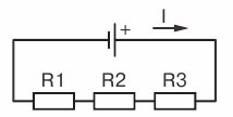
Rice 1… Series connection of resistances
How do we determine the total resistance of a circuit if we already know all the resistances connected to it in series? Using the position that the voltage U at the terminals of the current source is equal to the sum of the voltage drops in the circuit sections, we can write:
U = U1 + U2 + U3
where
U1 = IR1 U2 = IR2 and U3 = IR3
or
IR = IR1 + IR2 + IR3
Carrying out the right-hand side of the equality I in parentheses, we get IR = I (R1 + R2 + R3).
Now we divide both sides of the equality by I, finally we will have R = R1 + R2 + R3
Thus we came to the conclusion that when the resistances are connected in series, the total resistance of the entire circuit is equal to the sum of the resistances of the individual sections.
Let us verify this conclusion with the following example. Take three constant resistances whose values are known (eg R1 == 10 ohms, R2 = 20 ohms and R3 = 50 ohms). Let's connect them in series (Fig. 2) and connect to a current source whose EMF is 60 V (internal resistance of the current source neglected).
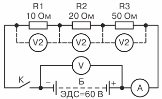
Rice. 2. Example of series connection of three resistances
Let's calculate what readings should be given by connected devices as shown in the diagram if we close the circuit. Determine the external resistance of the circuit: R = 10 + 20 + 50 = 80 ohms.
Find the current in the circuit Ohm's Law: 60 / 80= 0.75 A.
Knowing the current in the circuit and the resistance of its sections, we determine the voltage drop in each section of the circuit U1 = 0.75x 10 = 7.5 V, U2 = 0.75 x 20 = 15 V, U3 = 0.75 x 50 = 37.5V.
Knowing the voltage drop in the sections, we determine the total voltage drop in the external circuit, that is, the voltage at the terminals of the current source U = 7.5 + 15 + 37.5 = 60 V.
We get in such a way that U = 60 V, i.e. the non-existent equality of the EMF of the current source and its voltage. This is explained by the fact that we have neglected the internal resistance of the current source.
Having closed the K key, we can convince ourselves from the tools that our calculations are approximately correct.
Parallel connection of resistors
Take two constant resistances R1 and R2 and connect them so that the origin of these resistances is included in one common point a and the ends are in another common point b. By then connecting points a and b with a current source, we get a closed electrical circuit. This connection of resistances is called a parallel connection.
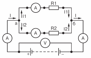
Figure 3. Parallel connection of resistances
Let's trace the current flow in this circuit. From the positive pole of the current source through the connecting wire, the current will reach point a. At point a it branches, because here the circuit itself branches into two separate branches: the first branch with resistance R1 and the second with resistance R2. Let us denote the currents in these branches by I1 and Az2, respectively. Each of these currents will take its own branch to point b. At this point the currents will merge into a single current that will reach the negative pole of the current source.
Thus, when resistances are connected in parallel, a branch circuit is obtained. Let's see what will be the ratio between the currents in our circuit.
Connect the ammeter between the positive pole of the current source (+) and point a and note its reading. Then, connecting the ammeter (shown in the figure with the dotted line) in the connecting wire point b with the negative pole of the current source (-), we note that the device will show the same magnitude of current strength.
It means circuit current before its branching (to point a) is equal to the strength of the current after branching the circuit (after point b).
Now we will turn on the ammeter in turn in each branch of the circuit, memorizing the readings of the device. Let the ammeter show the current in the first branch I1, and in the second - Az2.By adding these two ammeter readings, we obtain a total current equal in magnitude to the current Iz before branching (to point a).
Therefore, the strength of the current flowing to the branch point is equal to the sum of the strengths of the currents flowing from that point. I = I1 + I2 Expressing this by the formula, we get
This ratio, which is of great practical importance, is called the branched-chain law.
Let us now consider what will be the ratio between the currents in the branches.
Let's connect a voltmeter between points a and b and see what it shows. First, the voltmeter will show the voltage of the current source as it is connected, as can be seen from fig. 3directly to the power source terminals. Second, the voltmeter will show a voltage drop. U1 and U2 on resistors R1 and R2 as it is connected to the start and end of each resistance.
Therefore, when resistances are connected in parallel, the voltage across the current source terminals is equal to the voltage drop across each resistance.
This allows us to write that U = U1 = U2,
where U is the terminal voltage of the current source; U1 — voltage drop of resistance R1, U2 — voltage drop of resistance R2. Recall that the voltage drop across a section of a circuit is numerically equal to the product of the current flowing through that section by the section resistance U = IR.
Therefore, for each branch you can write: U1 = I1R1 and U2 = I2R2, but since U1 = U2, then I1R1 = I2R2.
Applying the rule of proportion to this expression, we get I1 / I2 = U2 / U1 that is, the current in the first branch will be as many times more (or less) than the current in the second branch, how many times the resistance of the first branch is less (or more) than the resistance of the second branch.
So, we have come to an important conclusion which is that with parallel connection of resistances, the total circuit current branches into currents inversely proportional to the resistance values of the parallel branches. In other words, the higher the resistance of the branch, the less current will flow through it and, conversely, the lower the resistance of the branch, the greater the current will flow through that branch.
Let's check the correctness of this dependency on the following example. Let's put together a circuit consisting of two parallel connected resistances R1 and R2 connected to a power source. Let R1 = 10 ohms, R2 = 20 ohms and U = 3 V.
Let's first calculate what the ammeter connected to each branch will show us:
I1 = U / R1 = 3/10 = 0.3 A = 300 mA
Az2 = U / R2 = 3/20 = 0.15 A = 150 mA
Total current in the circuit I = I1 +I2 = 300 + 150 = 450 mA
Our calculation confirms that when resistances are connected in parallel, the current in the circuit branches inversely proportional to the resistances.
Really, R1 == 10 ohms is half the size of R2 = 20 ohms, while I1 = 300mA twice I2 = 150mA. Total current in the circuit I = 450 mA divided into two parts, so that the greater part of it (I1 = 300 mA) passed through the lower resistance (R1 = 10 Ohm) and the smaller part (R2 = 150 mA) - through a greater resistance (R2 = 20 ohms).
This branching of current into parallel branches is similar to the flow of liquid through pipes.Imagine a pipe A that at some point branches into two pipes B and C of different diameters (Fig. 4). Since the diameter of pipe B is larger than the diameter of pipes C, more water will flow through pipe B at the same time than through pipe C, which has a greater resistance to water flow.
Rice. 4… Less water will pass through a thin pipe in the same amount of time than through a thick one.
Let us now consider what will be the total resistance of an external circuit consisting of two resistances connected in parallel.
By this, the total resistance of the external circuit should be understood as such a resistance that could replace both parallel-connected resistances at a given circuit voltage without changing the current before branching. This resistance is called equivalent resistance.
Let us return to the circuit shown in Fig. 3 and see what the equivalent resistance of two resistors connected in parallel will be. Applying Ohm's law to this circuit, we can write: I = U / R, where I Is the current in the external circuit (up to the branch point), U is the voltage of the external circuit, R is the resistance of the external circuit, that is, the equivalent resistance.
Similarly, for each branch I1 = U1 / R1, I2 = U2 / R2, where I1 and I2 — currents in the branches; U1 and U2 is the voltage in the branches; R1 and R2 — branch resistance.
According to the branch circuit law: I = I1 + I2
Substituting the values of the currents, we get U / R = U1 / R1 + U2 / R2
Since with parallel connection U = U1 = U2, then we can write U / R = U / R1 + U / R2
Performing U on the right-hand side of the equation outside the parentheses, we get U / R = U (1 / R1 + 1 / R2)
Now dividing both sides of the equality by U, we finally have 1 / R= 1 / R1 + 1 / R2
Remembering that conductivity is the reciprocal value of resistance, we can say that in the resulting formula 1 / R — conductivity of the external circuit; 1 / R1 the conductivity of the first branch; 1 / R2- the conductivity of the second branch.
Based on this formula, we conclude: when they are connected in parallel, the conductance of the external circuit is equal to the sum of the conductances of the individual branches.
Therefore, in order to determine the equivalent resistance of the resistances connected in parallel, it is necessary to determine the conductivity of the circuit and take the value opposite to it.
It also follows from the formula that the circuit conductance is greater than the conductance of each branch, which means that the equivalent resistance of the external circuit is less than the smallest of the resistances connected in parallel.
Considering the case of parallel connection of resistances, we took the simplest circuit consisting of two branches. In practice, however, there may be cases where the circuit consists of three or more parallel branches. What should we do in these cases?
It turns out that all the obtained connections remain valid for a circuit consisting of any number of resistances connected in parallel.
To verify this, consider the following example.
Let's take three resistances R1 = 10 Ohm, R2 = 20 Ohm and R3 = 60 Ohm and connect them in parallel. Determine the equivalent resistance of the circuit (Fig. 5).
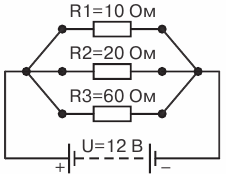
Rice. 5. Circuit with three parallel connected resistances
Applying this circuit formula 1 / R= 1 / R1 + 1 / R2, we can write 1 / R= 1 / R1 + 1 / R2 + 1 / R3 and, substituting the known values, we get 1 / R= 1 / 10 + 1 / 20 + 1 / 60
We add these fractions: 1 /R = 10/60 = 1/6, that is, the conductivity of the circuit is 1 / R = 1/6 Therefore, equivalent resistance R = 6 ohms.
Therefore, the equivalent resistance is less than the smallest of the resistances connected in parallel in the circuit, the smaller resistance R1.
Let us now see if this resistance is really equivalent, that is, such that it can replace the resistances of 10, 20 and 60 ohms connected in parallel without changing the current strength before branching the circuit.
Assume that the voltage of the external circuit, and hence the voltage in the resistances R1, R2, R3 is equal to 12 V. Then the strength of the currents in the branches will be: I1 = U / R1 = 12/10 = 1.2 A. Az2 = U / R2 = 12 / 20 = 1.6 A. Az3 = U / R1 = 12 / 60 = 0.2 A
We obtain the total current in the circuit using the formula I = I1 + I2 + I3 =1.2 + 0.6 + 0.2 = 2 A.
Let's check, using the formula of Ohm's law, whether a current of 2 A will be obtained in the circuit if, instead of three known parallel resistances, one equivalent resistance of 6 ohms is included.
I = U/R= 12 / 6 = 2 A
As you can see, the R = 6 Ohm resistance we found is indeed equivalent for this circuit.
This can be checked on meters if you assemble a circuit with the resistances we have taken, measure the current in the outer circuit (before branching), then replace the parallel connected resistances with a single 6 Ohm resistance and measure the current again.The readings of the ammeter in both cases will be approximately the same.
In practice, parallel connections can also occur, for which it is easier to calculate the equivalent resistance, that is, without first determining the conductances, the resistance can be found immediately.
For example, if two resistances are connected in parallel R1 and R2, then the formula 1 / R= 1 / R1 + 1 / R2 can be transformed like this: 1 / R = (R2 + R1) / R1 R2 and, solving the equality in relation of R, we get R = R1 NS R2 / (R1 + R2), i.e. when two resistances are connected in parallel, the equivalent resistance of the circuit is equal to the product of the resistances connected in parallel divided by their sum.