The principle of operation and the device of a single-phase transformer
Single-phase no-load transformer
Transformers in electrical engineering are called such electrical devices in which alternating current electrical energy from one fixed coil of wire is transferred to another fixed coil of wire that is not electrically connected to the first.
The link that transmits energy from one coil to the other is the magnetic flux, which interlocks with the two coils and is constantly changing in magnitude and direction.
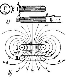
Rice. 1.
In fig. 1a shows the simplest transformer consisting of two windings / and / / arranged coaxially one above the other. To the coil / delivered alternating current from alternator D. This winding is called primary winding or primary winding. With a winding // called a secondary winding or secondary winding, a circuit is connected through receivers of electrical energy.
The principle of operation of the transformer
The action of the transformer is as follows. When current flows in the primary winding / it is created magnetic field, the lines of force of which penetrate not only into the winding that created them, but also partially into the secondary winding //. An approximate picture of the distribution of the lines of force created by the primary winding is shown in Fig. 1b.
As can be seen from the figure, all the lines of force are closed around the conductors of the coil /, but some of them in fig. 1b, the electric wires 1, 2, 3, 4 are also closed around the wires of the coil //. Thus coil // is magnetically coupled to coil / by means of magnetic field lines.
The degree of magnetic coupling of the coils /and //, with their coaxial arrangement, depends on the distance between them: the farther the coils are from each other, the less magnetic coupling between them, because the fewer the lines of force on the coil /stick to the coil //.
Since the coil / passes through, as we assume, single phase alternating current, that is, a current that changes over time according to some law, for example, according to the sine law, then the magnetic field created by it will also change over time according to the same law.
For example, when the current in the coil / passes through the largest value, then the magnetic flux generated by it also passes through the largest value; when the current in the coil / passes through zero, changing its direction, then the magnetic flux also passes through zero, also changing its direction.
As a result of changing the current in the coil /, both coils / and // are penetrated by a magnetic flux, constantly changing its value and direction. According to the basic law of electromagnetic induction, for every change in the magnetic flux penetrating the coil, an alternating current is induced in the coil electromotive force… In our case, the electromotive force of self-induction is induced in the coil /, and the electromotive force of mutual induction is induced in the coil //.
If the ends of the coil // are connected to a circuit of receivers of electrical energy (see Fig. 1a), then a current will appear in this circuit; therefore the receivers will receive electrical power. At the same time, energy will be directed to the winding /from the generator, almost equal to the energy given to the circuit by the winding //. In this way, electrical energy from one coil will be transmitted to the circuit of the second coil, which is completely unrelated to the first coil galvanically (metallic). In this case, the means of energy transmission is only an alternating magnetic flux.
Shown in fig. 1a, the transformer is very imperfect because there is little magnetic coupling between the primary winding /and the secondary winding //.
The magnetic coupling of two coils, generally speaking, is estimated by the ratio of the magnetic flux coupled to the two coils to the flux created by one coil.
Fig. 1b, it can be seen that only part of the field lines of the coil /is closed around the coil //. The other part of the power lines (in Fig. 1b — lines 6, 7, 8) is closed only around the coil /. These power lines are not at all involved in the transfer of electrical energy from the first coil to the second, they form the so-called stray field.
In order to increase the magnetic coupling between the primary and secondary windings and at the same time to reduce the magnetic resistance for the passage of the magnetic flux, the windings of technical transformers are placed on completely closed iron cores.
The first example of the implementation of transformers is shown schematically in fig. 2 single-phase transformer of the so-called rod type. Its primary and secondary coils c1 and c2 are located on iron rods a — a, connected at the ends with iron plates b — b, called yokes. In this way, two rods a, a and two yokes b, b form a closed iron ring, in which passes the magnetic flux blocked with the primary and secondary windings. This iron ring is called the core of the transformer.
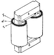 Rice. 2.
The second embodiment of transformers is shown schematically in fig. 3 single-phase transformer of the so-called armored type. In this transformer the primary and secondary windings c, each consisting of a row of flat windings, are placed on a core formed by two bars of two iron rings a and b. The rings a and b surrounding the windings cover them almost entirely with armor, therefore the described transformer is called armored. The magnetic flux passing inside the coils c is divided into two equal parts, each of which is enclosed in its own iron ring.
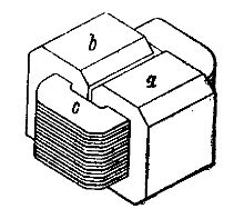
Rice. 3
The use of closed iron magnetic circuits in transformers achieves a significant reduction in leakage current. In such transformers, the fluxes connected to the primary and secondary windings are almost equal to each other. If we assume that the primary and secondary windings are penetrated by the same magnetic flux, we can write expressions based on the total induced shock for the instantaneous values of the electromotive forces of the windings:

In these expressions, w1 and w2 — the number of turns of the primary and secondary windings, and dFt is the magnitude of change in the penetrating winding of the magnetic flux per time element dt, therefore there is a rate of change of the magnetic flux. From the last expressions, the following relation can be obtained:

i.e. indicated in the primary and secondary windings / and // the momentary electromotive forces are related to each other in the same way as the number of turns of the coils. The last conclusion is valid not only with respect to the instantaneous values of electromotive forces, but also with respect to their greatest and effective values.
The electromotive force induced in the primary winding, as an electromotive force of self-induction, almost completely balances the voltage applied to the same winding... If by E1 and U1 you indicate the effective values \u200b\u200bof the electromotive force of the primary winding and the voltage applied to it, then you can write :

The electromotive force induced in the secondary winding, in the case under consideration, is equal to the voltage across the ends of this winding.
If, like the previous one, through E2 and U2 you indicate the effective values of the electromotive force of the secondary winding and the voltage at its ends, then you can write:

Therefore, by applying some voltage to one winding of the transformer, you can get any voltage at the ends of the other coil, you just need to take a suitable ratio between the number of turns of these coils. This is what the main property of the transformer is.
The ratio of the number of turns of the primary winding to the number of turns of the secondary winding is called transformation ratio of the transformer... We will denote the transformation coefficient kT.
Therefore, one can write:
A transformer whose transformation ratio is less than one is called a step-up transformer, because the voltage of the secondary winding, or the so-called secondary voltage, is greater than the voltage of the primary winding, or the so-called primary voltage. A transformer with a transformation ratio greater than one is called a step-down transformer, since its secondary voltage is less than the primary.
Operation of a single-phase transformer under load
During the idling of the transformer, the magnetic flux is created by the primary winding current or rather by the magnetomotive force of the primary winding. Since the magnetic circuit of the transformer is made of iron and therefore has a low magnetic resistance, and the number of turns of the primary winding is generally assumed to be large, the no-load current of the transformer is small, it is 5-10% of normal.
If you close the secondary coil to some resistance, then with the appearance of current in the secondary coil, the magnetomotive force of this coil will also appear.
According to Lenz's law, the magnetomotive force of the secondary coil acts against the magnetomotive force of the primary coil
It seems that the magnetic flux in this case should decrease, but if a constant voltage is applied to the primary winding, then there will be almost no decrease in magnetic flux.
In fact, the electromotive force induced in the primary winding when the transformer is loaded is almost equal to the applied voltage. This electromotive force is proportional to the magnetic flux.Therefore, if the primary voltage is constant in magnitude, then the electromotive force under load should remain nearly the same as it was during no-load operation of the transformer. This circumstance leads to almost complete constancy of the magnetic flux under any load.
 Thus, at a constant value of the primary voltage, the magnetic flux of the transformer hardly changes with the change of load and can be assumed to be equal to the magnetic flux during no-load operation.
The magnetic flux of the transformer can maintain its value under load only because as a current appears in the secondary winding, the current in the primary winding also increases, so much so that the difference between the magnetomotive forces or ampere turns of the primary and secondary windings remains nearly equal to the magnetomotive force or ampere-turns during idling ... Thus, the appearance of a demagnetizing magnetomotive force or ampere-turns in the secondary winding is accompanied by an automatic increase in the magnetomotive force of the primary winding.
Since, as mentioned above, a small magnetomotive force is required to create a transformer magnetic flux, it can be said that an increase in the secondary magnetomotive force is accompanied by an increase in the primary magnetomotive force, which is almost the same in magnitude.
Therefore, one can write:

From this equality, the second main characteristic of the transformer is obtained, namely the ratio:

where kt is the transformation factor.
Therefore, the ratio of the currents of the primary and secondary windings of the transformer is equal to one divided by the transformation ratio.
So, the main characteristics of the transformer have a relationship

and

If we multiply the left sides of the relationship by each other and the right sides by each other, we get

and

The last equality gives the third characteristic of the transformer, which can be expressed in words like this: the power delivered by the secondary winding of the transformer in volt-amperes is almost equal to the power delivered to the primary winding also in volt-amperes.
If we ignore the energy losses in the copper of the windings and in the iron of the transformer core, then we can say that all the power supplied to the primary winding of the transformer from the power source is transferred to its secondary winding, and the transmitter is the magnetic flux.