AC capacitor
 Let's assemble the circuit with capacitor, where the alternator generates a sinusoidal voltage. Let's analyze sequentially what will happen in the circuit when we close the switch. We will consider the initial moment when the generator voltage is equal to zero.
During the first quarter of the period, the voltage across the generator terminals will increase, starting from zero, and the capacitor will begin to charge. A current will appear in the circuit, however, at the first moment of charging the capacitor, despite the fact that the voltage on its plates has just appeared and is still very small, the current in the circuit (charging current) will be the largest . As the charge on the capacitor increases, the current in the circuit decreases and reaches zero at the moment when the capacitor is fully charged. In this case, the voltage on the plates of the capacitor, strictly following the voltage of the generator, becomes at this moment maximum, but with the opposite sign, that is, it is directed to the voltage of the generator.
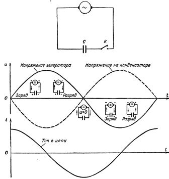
Rice. 1. Change of current and voltage in a circuit with capacitance
In this way, the current rushes with the greatest force into a capacitor for free, but immediately begins to decrease when the plates of the capacitor are filled with charges and fall to zero, fully charging it.
Let us compare this phenomenon with what happens to the flow of water in a pipe connecting two communicating vessels (Fig. 2), one of which is full and the other empty. One has only to press the valve blocking the water path, as water immediately rushes from the left vessel under great pressure through the pipe into the empty right vessel. Immediately, however, the water pressure in the pipe will gradually begin to weaken due to the equalization of the levels in the vessels and will drop to zero. The water flow will stop.
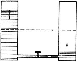
Rice. 2. The change in water pressure in the pipe connecting the communication vessels is similar to the change in current in the circuit during the charging of the capacitor
Similarly, the current first rushes into an uncharged capacitor and then gradually weakens as it charges.
As the second quarter of the period begins, when the generator voltage initially starts slowly and then decreases more and more rapidly, the charged capacitor will discharge to the generator, causing a discharge current in the circuit. As the generator voltage decreases, the capacitor discharges more and more and the discharge current in the circuit increases. The direction of the discharge current in this quarter of the period is opposite to the direction of the charge current in the first quarter of the period. Accordingly, the current curve that has passed the zero value is now located below the time axis.
By the end of the first half-cycle, the generator voltage, as well as the capacitor voltage, rapidly approaches zero and the circuit current slowly reaches its maximum value. Given that the value of the current in the circuit is greater, the greater the value of the charge carried in the circuit, it will become clear why the current reaches its maximum when the voltage on the plates of the capacitor, and therefore the charge on capacitor, rapidly decreases.
With the beginning of the third quarter of the period, the capacitor begins to charge again, but the polarity of its plates, as well as the polarity of the generator, changes "and vice versa, and the current, continuing to flow in the same direction, begins to decrease as the capacitor charges. the end of the third quarter of the period, when the generator and capacitor voltages reach their maximum, the current goes to zero.
During the last quarter of the period, the voltage, decreasing, falls to zero, and the current, having changed its direction in the circuit, reaches its maximum value. Here the period ends, after which the next one begins, exactly repeating the previous one, and so on.
Thus, under the action of the alternating voltage of the generator, the capacitor is charged twice during the period (the first and third quarter of the period) and discharged twice (the second and fourth quarter of the period). But since they alternate one by one capacitor charges and discharges accompanied each time by the passage of the charging and discharging current through the circuit, then we can conclude that alternating current.
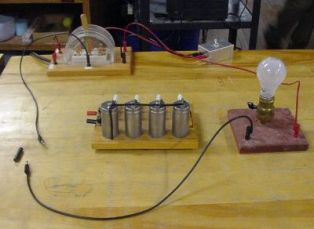
You can check this in the following simple experiment. Connect a 4-6 microfarad capacitor to the mains via a 25 W light bulb.The light will come on and will not go out until the circuit is broken. This suggests that an alternating current has passed through the circuit with the capacitance. Of course, it does not pass through the dielectric of the capacitor, but at any moment in time represents either a charge current or a capacitor discharge current.
As we know, the dielectric is polarized under the action of an electric field arising in it when the capacitor is charged, and its polarization disappears when the capacitor is discharged.
In this case, the dielectric with the displacement current arising in it serves for the alternating current as a kind of continuation of the circuit, and for the constant it breaks the circuit. But the displacement current is formed only within the dielectric of the capacitor, and therefore the transfer of charges along the circuit does not occur.
The resistance offered by an AC capacitor depends on the value of the capacitor's capacitance and the frequency of the current.
The greater the capacity of the capacitor, the greater the charge on the circuit during charging and discharging of the capacitor and, accordingly, the greater the current in the circuit. An increase in the current in the circuit indicates that its resistance has decreased.
Therefore, as the capacitance increases, the resistance of the circuit to alternating current decreases.
It's growing current frequency increases the amount of charge carried in the circuit because the charge (as well as the discharge) of the capacitor must occur faster than at low frequency. At the same time, an increase in the amount of transferred charge per unit time is equivalent to an increase in the current in the circuit and, therefore, to a decrease in its resistance.
If we somehow gradually reduce the frequency of the alternating current and reduce the current to direct current, then the resistance of the capacitor included in the circuit will gradually increase and become infinitely large (breaking the circuit) until it appears in constant current circuit.
Therefore, as the frequency increases, the resistance of the capacitor to alternating current decreases.
Just as the resistance of a coil to an alternating current is called inductive, the resistance of a capacitor is called capacitive.
Therefore, the capacitive resistance is greater, the lower the capacity of the circuit and the frequency of the current that feeds it.
Capacitive resistance is denoted as Xc and is measured in ohms.
The dependence of the capacitive resistance on the frequency of the current and the capacity of the circuit is determined by the formula Xc = 1 /ωC, where ω is a circular frequency equal to the product of 2πe, C is the capacity of the circuit in farads.
Capacitive resistance, like inductive resistance, has a reactive nature, since the capacitor does not consume the energy of the current source.
formula Ohm's Law for a capacitive circuit it has the form I = U / Xc, where I and U — effective values of current and voltage; Xc is the capacitive resistance of the circuit.
The property of capacitors to provide high resistance to low-frequency currents and to easily pass high-frequency currents is widely used in communication equipment circuits.
With the help of capacitors, for example, separation of constant currents and low-frequency currents from high-frequency currents, necessary for the operation of the circuits, is achieved.
If it is necessary to block the path of low-frequency current in the high-frequency part of the circuit, a small capacitor is connected in series. It offers great resistance to low frequency current and at the same time easily passes high frequency current.
If it is necessary to prevent high-frequency current, for example, in the power circuit of the radio station, then a capacitor of large capacity is used, connected in parallel with the current source. In this case, the high-frequency current passes through the capacitor, bypassing the power supply circuit of the radio station.
Active resistance and capacitor in the AC circuit
In practice, cases are often observed when in a series circuit with a capacitance active resistance is included. The total resistance of the circuit in this case is determined by the formula
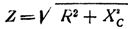
Therefore, the total resistance of a circuit consisting of active and capacitive AC resistance is equal to the square root of the sum of the squares of the active and capacitive resistance of this circuit.
Ohm's law remains valid for this I = U / Z circuit as well.
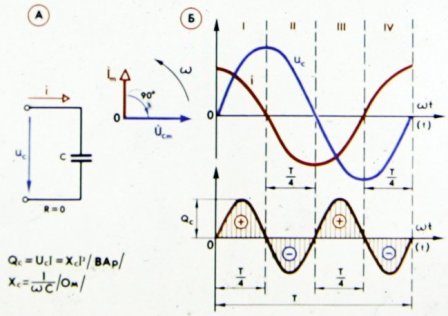
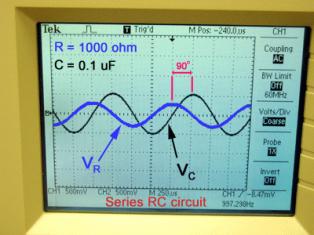
In fig. 3 shows the curves characterizing the phase relationship between current and voltage in a circuit containing capacitive and active resistance.
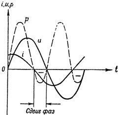
Rice. 3. Current, voltage and power in a circuit with a capacitor and an active resistance
As can be seen from the figure, the current in this case increases the voltage not by a quarter of a period, but by less, since the active resistance violates the purely capacitive (reactive) nature of the circuit, as evidenced by the reduced phase shift. Now the voltage at the circuit terminals is defined as the sum of two components: the reactive component of the voltage tive, will overcome the capacitive resistance of the circuit and the active component of the voltage, overcoming its active resistance.
The greater the active resistance of the circuit, the smaller the phase shift between current and voltage.
The curve of the power change in the circuit (see Fig. 3) twice during the period acquired a negative sign, which, as we already know, is a consequence of the reactive nature of the circuit. The less reactive the circuit, the smaller the phase shift between current and voltage, and the more current source power that circuit consumes.
Read also: Voltage resonance