The principle of operation and the device of three-phase transformers
Three-phase current can be transformed by three completely separate single-phase transformers. In this case, the windings of all three phases are not magnetically connected to each other: each phase has its own magnetic circuit. But the same three-phase current can be transformed with one three-phase transformer, in which the windings of all three phases are magnetically connected to each other, since they have a common magnetic circuit.
To clarify the principle of operation and device of a three-phase transformer, imagine three single phase transformer, attached to each other so that their three rods form one common central rod (Fig. 1). On each of the other three bars, primary and secondary windings are superimposed (in Fig. 1, the secondary windings are not shown).
Assume that the primary windings on all legs of the transformer are exactly the same and wound in the same direction (in Fig. 1, the primary windings are wound clockwise when viewed from above).We connect all the upper ends of the coils to neutral O and bring the lower ends of the coils to the three terminals of the three-phase network.
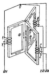
Picture 1.
The currents in the transformer windings will create time-varying magnetic fluxes, each of which will close in its own magnetic circuit. In the central composite rod, the magnetic fluxes will add up to zero in total because these fluxes are created by symmetrical three-phase currents, relative to which we know that the sum of their instantaneous values is zero at all times.
For example, if the current in the coil AX I, was the largest and took place in the indicated in fig. 1 direction, then the magnetic flux would be equal to its largest value Ф and was directed into the central composite rod from top to bottom. In the other two coils BY and CZ, the currents I2 and Az3 at the same moment in time are equal to half of the highest current and have the opposite direction with respect to the current in the coil AX (this is the property of three-phase currents). For this reason, in the rods of the BY and CZ coils, the magnetic fluxes will be equal to half the maximum flux, and in the central composite rod they will have the opposite direction with respect to the flux of the AX coil. The sum of flows at the moment in question is zero. The same goes for any other moment.
No flow in the center bar does not mean no flow in the other bars. If we destroy the central rod and connect the upper and lower yokes in common yokes (see Fig. 2), then the flux of the coil AX will find its way through the cores of the coils BY and CZ, and the magnetomotive forces of these coils will add together with the magnetomotive force of coil AX. In this case, we would get a three-phase transformer with a common magnetic circuit for all three phases.
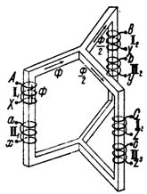
Figure 2.
Since the currents in the coils are phase-shifted by 1/3 of the period, the magnetic fluxes produced by them are also time-shifted by 1/3 of the period, i.e. the largest values of the magnetic fluxes in the rods and coils follow one another after 1/3 of the period...
The consequence of the phase shift of the magnetic fluxes in the cores by 1/3 of the period is the same phase shift and the electromotive forces induced in both the primary and secondary windings imposed on the bars. The electromotive forces of the primary windings almost balance the applied three-phase voltage. The electromotive forces of the secondary windings, with the correct connection of the ends of the coils, give a three-phase secondary voltage which is fed into the secondary circuit.
As for the construction of the magnetic circuit, three-phase transformers, like single-phase ones, are divided into rod figs. 2. and armored.
Three-phase rod transformers are classified into:
a) transformers with symmetrical magnetic circuit and
b) transformers with an asymmetric magnetic circuit.
In fig. 3 schematically shows a slide transformer with a symmetrical magnetic circuit, and in fig. 4 shows a rod transformer with an unbalanced magnetic circuit. As seen by the three iron bars 1, 2 and 3, clamped above and below by iron yoke plates. There are primary I and secondary II coils of one phase of the transformer on each leg.
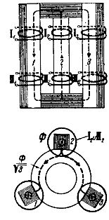 Figure 3.
In the first transformer, the rods are located at the vertices of the angles of an equilateral triangle; the second transformer has the bars in the same plane.
The arrangement of the rods at the vertices of the corners of an equilateral triangle gives equal magnetic resistances for the magnetic fluxes of all three phases, since the paths of these fluxes are the same. In fact, the magnetic fluxes of the three phases pass separately through one vertical rod completely and through the other two rods halfway.
In fig. 3 the dotted line shows the ways of closing the magnetic flux of the rod phase 2. It is easy to see that for the fluxes of the phases of rods 1 and 3, the ways of closing their magnetic fluxes are exactly the same. This means that the transformer under consideration has the same magnetic resistances for the fluxes.
The arrangement of the rods in one plane leads to the fact that the magnetic resistance for the flux of the middle phase (in Fig. 4 for the phase of the rod 2) is less than for the fluxes of the end phases (in Fig. 4 — for the phases of the rods 1 and 3).
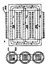
Figure 4.
In fact, the magnetic fluxes of the end phases move along slightly longer paths than the flux of the middle phase. Moreover, the flow of the terminal phases leaving their rods passes entirely in one half of the yoke and only in the other half (after branching in the middle rod) half of it passes. The mid-phase flow at the outlet of the vertical rod immediately splits into two halves, and therefore only half of the mid-phase flow passes into the two parts of the yoke.
 Thus, the fluxes of the end phases saturate the yoke to a greater extent than the flux of the middle phase, and therefore the magnetic resistance for the fluxes of the end phases is greater than for the flux of the middle phase.
The consequence of the inequality of the magnetic resistances for the fluxes of different phases of a three-phase transformer is the inequality of the no-load currents in individual phases at the same phase voltage.
However, with low yoke iron saturation and good rod iron assembly, this current inequality is negligible. Because Since the construction of transformers with an asymmetric magnetic circuit is much simpler than that of a transformer with a symmetrical magnetic circuit, the first transformers turned out to be mostly used. Symmetrical magnetic circuit transformers are rare.
Considering fig. 3 and 4 and assuming that currents flow through all three phases, it is easy to see that all phases are magnetically coupled to each other. This means that the magnetomotive forces of the individual phases influence each other, which we do not have when the three-phase current is transformed by three single-phase transformers.
The second group of three-phase transformers are armored transformers. An armored transformer can be considered as if it is composed of three single-phase armored transformers attached to each other with a yoke.
In fig. 5 schematically depicts an armored three-phase transformer with a vertically located inner core. From the figure it is easy to see that through the planes AB and CD it can be divided into three single-phase armored transformers, the magnetic fluxes of which can be closed each in its own magnetic circuit . The magnetic flux paths in fig. 5 are indicated by dashed lines.
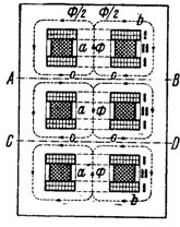
Figure 5.
As can be seen from the figure, in the middle vertical rods a, on which the primary I and secondary II windings of the same phase are superimposed, the full flux passes, while in the yokes b-b and the side walls half of the flux passes. At the same induction, the cross-sections of the yoke and the sidewalls should be half the cross-section of the middle rod a.
As for the magnetic flux in the intermediate parts c — c, its value, as we will see below, depends on the method of inclusion of the middle phase.
The main advantage of armature transformers over rod transformers is the short closing paths of the magnetic flux and therefore the low no-load currents.
The disadvantages of armored transformers include, firstly, the low availability of windings for repair, due to the fact that they are surrounded by iron, and secondly, the worst conditions for cooling the winding — for the same reason.
In rod-type transformers, the windings are almost completely open and therefore more accessible for inspection and repair, as well as for the cooling medium.
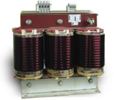
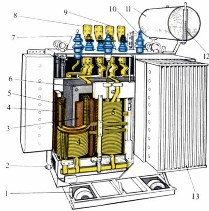 Three-phase oil-filled transformer with tubular tank: 1 — pulleys, 2 — oil drain valve, 3 — insulating cylinder, 4 — high voltage winding, 5 — low voltage winding, 6 — core, 7 — thermometer, 8 — terminals for low voltage, 9 — high voltage terminals, 10 — oil container, 11 — gas relays, 12 — oil level indicator, 13 — radiators.
More details about the device of three-phase transformers: Power transformers — device and principle of operation