Voltage resonance
If the AC circuit is connected in series inductor and capacitor, then they in their own way affect the generator feeding the circuit and the phase connections between current and voltage.
An inductor introduces a phase shift where the current lags the voltage by a quarter of a period, while a capacitor, on the contrary, makes the voltage in the circuit lag the current by a quarter of a period. Thus, the effect of inductive resistance on the phase shift between current and voltage in a circuit is opposite to the effect of capacitive resistance.
This leads to the fact that the total phase shift between current and voltage in the circuit depends on the ratio of the inductive and capacitive resistance values.
If the value of the capacitive resistance of the circuit is greater than the inductive one, then the circuit is capacitive in nature, that is, the voltage lags behind the current in phase. If, on the contrary, the inductive resistance of the circuit is greater than the capacitive one, then the voltage leads the current and therefore the circuit is inductive.
The total reactance Xtot of the circuit we are considering is determined by adding the inductive resistance of the coil XL and the capacitive resistance of the capacitor XC.
But since the action of these resistances in the circuit is opposite, then one of them, namely Xc, is assigned a minus sign, and the total reactance is determined by the formula:


Apply to this circuit Ohm's Law, we get:

This formula can be transformed as follows:

In the resulting equation, AzxL — the effective value of the component of the total voltage of the circuit, which will overcome the inductive resistance of the circuit, and AzNSC — the effective value of the component of the total voltage of the circuit, which will overcome the capacitive resistance.
Thus, the total voltage of a circuit consisting of a series connection of a coil and a capacitor can be considered as consisting of two terms, the values of which depend on the values of the inductive and capacitive resistance of the circuit.
We believed that such a circuit has no active resistance. However, in cases where the active resistance of the circuit is no longer so small as to be negligible, the total resistance of the circuit is determined by the following formula:

where R is the total active resistance of the circuit, XL -NSC — its total reactance. Moving to the formula of Ohm's law, we have the right to write:

AC voltage resonance
Inductive and capacitive resistances connected in series cause less phase shift between current and voltage in an AC circuit than if they were included in the circuit separately.
In other words, from the simultaneous action of these two reactions of a different nature in the circuit, compensation (mutual destruction) of the phase shift occurs.
Full compensation, ie. complete elimination of the phase shift between current and voltage in such a circuit will occur when the inductive resistance is equal to the capacitive resistance of the circuit, i.e. when XL = XC or, which is the same, when ωL = 1 / ωC.
In this case, the circuit will behave as a purely active resistance, that is, as if it has neither a coil nor a capacitor. The value of this resistance is determined by the sum of the active resistances of the coil and the connecting wires. At which effective current in the circuit will be the largest and is determined by the Ohm's law formula I = U / Rwhere Z is now replaced by R.
At the same time, the voltages acting on the coil UL = AzxL and on the capacitor Uc = AzNSCC will be equal and will be as large as possible. With low active resistance of the circuit, these voltages can many times exceed the total voltage U of the circuit terminals. This interesting phenomenon is called voltage resonance in electrical engineering.
In fig. 1 shows the curves of voltages, currents and power at resonance voltages in the circuit.
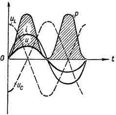
Graph of voltage current and power at voltage resonance
It should be borne in mind that the resistances XL and C are variables that depend on the frequency of the current and it is worth at least slightly changing its frequency, for example, increasing it as XL = ωL will increase, and XSC = = 1 / ωC will will decrease and thus the voltage resonance in the circuit will immediately be disturbed, while along with the active resistance, the reactance will appear in the circuit. The same will happen if you change the value of the inductance or capacitance of the circuit.
With voltage resonance, the power of the current source will be spent only to overcome the active resistance of the circuit, that is, to heat the wires.
In fact, in a circuit with a single inductive coil, energy fluctuations occur, i.e. periodic transfer of energy from the generator to magnetic field coils. In a circuit with a capacitor, the same thing happens, but because of the energy of the capacitor's electric field. In a circuit with a capacitor and an inductor at voltage resonance (ХL = XС) the energy, once stored by the circuit, periodically passes from the coil to the capacitor and vice versa, and only the energy consumption necessary to overcome the active resistance of the circuit falls on the share of the source of current. Therefore, the energy exchange takes place between the capacitor and the coil almost without the participation of the generator.
One only has to break a voltage resonance by value, how the energy of the magnetic field of the coil becomes unequal to the energy of the electric field of the capacitor, and in the process of energy exchange between these fields, an excess of energy will appear, which will periodically flow out from the source in the circuit, then feed it back to it in the circuit.
This phenomenon is very similar to what happens in a clockwork. A clock's pendulum would be able to oscillate continuously without the aid of a spring (or a weight in a clock walker) if it were not for the forces of friction that slow its motion.
The spring, by transmitting some of its energy to the pendulum at the right moment, helps it to overcome the forces of friction, thus achieving continuity of oscillation.
Similarly, in an electric circuit, when resonance occurs in it, the current source spends its energy only to overcome the active resistance of the circuit, thus assisting the oscillatory process in it.
Thus we come to the conclusion that an alternating current circuit, consisting of a generator and a series-connected inductor and capacitor, under certain conditions XL = XС becomes an oscillating system... This circuit was named an oscillating circuit.
From the equation XL = XС it is possible to determine the values of the frequency of the generator at which the phenomenon of voltage resonance occurs:

Meaning capacitance and inductance of the circuit where voltage resonance occurs:


Thus, changing any of these three quantities (eres, L and C), it is possible to cause voltage resonance in the circuit, that is, to turn the circuit into an oscillating circuit.
An example of a useful application of voltage resonance: The input circuit of a receiver is adjusted by a variable capacitor (or variometer) in such a way that voltage resonance occurs in it. This achieves a large increase in the coil voltage required for normal receiver operation compared to the circuit voltage created by the antenna.
Along with the useful use of the phenomenon of voltage resonance in electrical engineering, there are often cases where voltage resonance is harmful. A large increase in the voltage in individual sections of the circuit (on the coil or on the capacitor) compared to the voltage of the generator can lead to damage of separate parts and measuring devices.