What is voltage loss and the causes of voltage loss
Loss of line voltage
To understand what voltage loss is, consider the voltage vector diagram of a three-phase AC line (Fig. 1) with a single load at the end of the line (Fig. 1)I).
Suppose that the current vector is decomposed into components Azi and AzP. In fig. 2 the phase voltage vectors at the end of the line are drawn to scale U3ph and current AziLing in phase by an angle φ2.
To get the voltage vector at the beginning of the line U1φ follows the vector at the end U2ph, draw the line voltage drop triangle (abc) on the voltage scale. For this, the vector ab, equal to the product of current and active resistance of the line (AzR), is located parallel to the current, and the vector b° C, equal to the product of current and inductive resistance of the line (AzX), is perpendicular to the current vector .Under these conditions, the straight line connecting points O and c corresponds to the magnitude and position in space of the stress vector at the beginning of the line (U1e) relative to the stress vector at the end of the line (U2e). Connecting the ends of the vectors U1f and U2e, we get the voltage drop vector of the linear impedance ac = IZ.
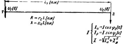
Rice. 1. Schematic with a single end-of-line load
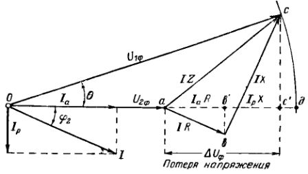
Rice. 2. Vector diagram of voltages for a line with a single load. Loss of line voltage.
Agree to call voltage loss the algebraic difference between the phase voltages at the beginning and end of the line, that is segment ad or almost equal segment ac '.
The vector diagram and the relationships derived from it show that the voltage loss depends on the parameters of the network, as well as on the active and reactive components of the current or load.
When calculating the amount of voltage loss in the network, the active resistance must always be taken into account, and the inductive resistance can be neglected in lighting networks and in networks made with cross-sections up to 6 mm2 and cables up to 35 mm2.
Determination of voltage loss in the network
The voltage loss for a three-phase system is usually indicated for linear quantities, which are determined by the formula
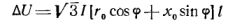
where l — length of the corresponding section of the network, km.
If we replace current with power, the formula will take the form:
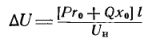
where P. — active power, B- reactive power, kVar; l — length of the section, km; Un — nominal network voltage, kV.
Change in line voltage
Allowable voltage drop
For each power receiver, a certain voltage loss... For example, induction motors have a voltage tolerance of ± 5% under normal conditions.This means that if the nominal voltage of this electric motor is 380 V, then the voltage U„extra = 1.05 Un = 380 x1.05 = 399 V and U»add = 0.95 Un = 380 x 0.95 = 361 V should be considered as the maximum allowable voltage values. Naturally, all intermediate voltages between the values 361 and 399 V will also satisfy the user and constitute a certain zone that can be called the zone of desired voltages.
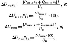
Since during the operation of the enterprise there is a constant change in the load (power or current flowing through the wires at a certain time of the day), then various voltage losses will occur in the network, varying from the highest corresponding values to the maximum load mode dUmax, to the smallest dUmin corresponding to the minimum load of the user.
To calculate the amount of these voltage losses, use the formula:
From the vector diagram of voltages (Fig. 2) it follows that the actual voltage of the receiver U2f can be obtained if we subtract the value dUf from the voltage at the beginning of the line U1f, or, switching to a linear, i.e. phase-to-phase voltage, we get U2 = U1 — dU
Calculation of voltage losses
An example. The consumer, consisting of asynchronous motors, is connected to the buses of the transformer substation of the enterprise, which maintain a constant voltage throughout the day U1 = 400 V.
The highest user load is noted at 11 am, while the voltage loss dUmax = 57 V, or dUmax% = 15%. The smallest consumer load corresponds to the lunch break, while dUmin — 15.2 V, or dUmin% = 4%.
It is necessary to determine the actual voltage at the user in the highest and lowest load modes and check that it is within the desired voltage range.
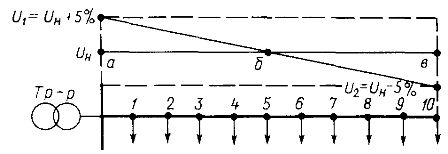
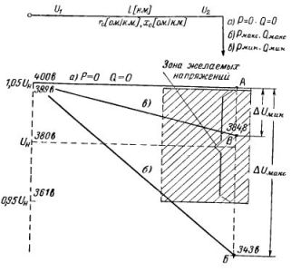 Rice. 3. Potential diagram for a line with a single load to determine the voltage loss
Answer. Determine the actual voltage values:
U2Max = U1 — dUmax = 400 — 57 = 343 V
U2min = U1 — dUmin = 400 — 15.2 = 384.8V
The desired voltage for asynchronous motors with Un = 380 V must meet the condition:
399 ≥ U2zhel ≥ 361
Substituting the calculated stress values into the inequality, we make sure that for the largest load mode the ratio 399> 343> 361 is not fulfilled, and for the smallest loads 399> 384.8> 361 is fulfilled.
Exit. In the mode of greatest loads, the loss of voltage is so great that the voltage at the user goes out of the zone of the desired voltages (decrease) and does not satisfy the user.
This example can be illustrated graphically by the potential diagram in Fig. 3. In the absence of current, the voltage at the user will be numerically equal to the voltage of the supply buses. Since the voltage drop is proportional to the length of the supply line, the voltage in the presence of a load changes along the line in a sloping straight line from the value U1 = 400 V to the value U2Max = 343 V and U2min = 384.8 V.
As can be seen from the diagram, the voltage at the highest load has left the zone of desired voltages (point B on the graph).
Thus, even with a constant voltage on the supply transformer busbars, sudden changes in the load can create an unacceptable voltage value at the receiver.
In addition, it may happen that when the load on the network changes from the highest load during the day to the lowest load at night, the power system itself will not be able to provide the necessary voltage at the transformer terminals. In both cases, means of local, mainly voltage change must be resorted to.
Loss of voltage in the transformer (in pictures)