Autotransformers — device, principles, advantages and disadvantages
Purpose, device and principle of operation of autotransformers
In some cases, it is necessary to vary the voltage over a small range. The easiest way to do this is not double winding transformersand single windings called autotransformers. If the transformation factor is slightly different from unity, then the difference between the magnitude of the currents in the primary and in the secondary windings will be small. What happens if you combine the two coils? You will get a diagram of an autotransformer (Fig. 1).
Autotransformers are classified as special purpose transformers. Autotransformers differ from transformers in that their low-voltage winding is part of the higher-voltage winding, that is, the circuits of these windings have not only a magnetic, but also a galvanic connection.
Depending on the inclusion of the windings of the autotransformer, an increase or decrease in voltage may occur.
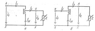
Rice.1 Schemes of single-phase autotransformers: a-step-down, b-step-up.
If you connect an alternating voltage source to points A and X, then an alternating magnetic flux will appear in the core. An EMF of the same magnitude will be induced in each of the coil turns. Obviously, between points a and X there will be an EMF equal to the EMF of one turn times the number of turns closed between points a and X.
If you attach to the coil at points a and X any load, then the secondary current I2 will pass through part of the coil and is between points a and X. But since the primary current passes through the same turns I1, then the two currents will add geometrically and a very small amount of current will flow along the section aX, determined by the difference between these currents. This allows a portion of the winding to be cut from small gauge wire to save copper. If we consider that this section makes up the majority of all turns, then the copper economy is very noticeable.
Thus, it is advisable to use autotransformers to slightly decrease or increase the voltage, when a reduced current is set in the winding part, which is common to both circuits of the autotransformer, which allows to do with a thinner wire and save non-ferrous metals. At the same time, the consumption of steel for the production of a magnetic circuit decreases, the cross-section of which is smaller than that of a transformer.
In electromagnetic energy converters - transformers - the transfer of energy from one coil to another is carried out by a magnetic field, the energy of which is concentrated in the magnetic circuit.In autotransformers, energy is transmitted both through a magnetic field and through an electrical connection between the primary and secondary windings.
Transformer and autotransformer
Autotransformers successfully compete with two-winding transformers when their transformation ratio is slightly different from unity and is more than 1.5 — 2. When the transformation ratio is above 3, autotransformers are not justified.
Structurally, autotransformers practically do not differ from transformers. There are two coils on the cores of the magnetic circuit. The leads are taken from two windings and a common point. Most autotransformer parts are structurally indistinguishable from transformer parts.
Laboratory autotransformers (LATR)
Autotransformers are also used in low-voltage networks as low-power laboratory voltage regulators (LATRs). In such autotransformers, voltage regulation is carried out by moving the sliding contact along the turns of the winding.
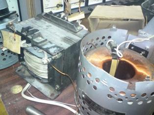
Laboratory-controlled single-phase autotransformers consist of an annular ferromagnetic magnetic circuit wrapped with a single layer of insulated copper wire (Fig. 2).
Several constant taps are made from this winding, which allows these devices to be used as step-down or step-up autotransformers with a certain constant transformation ratio. In addition, on the surface of the coil, cleaned of insulation, there is a narrow path along which the contact of the brush or roller moves to obtain a continuously adjustable secondary voltage ranging from zero to 250 V.
When adjacent turns are closed in LATR, no turn closing occurs because the line and load currents in the combined winding of the autotransformer are close to each other and in opposite directions.
Laboratory autotransformers are produced with a nominal power of 0.5; 1; 2; 5; 7.5 kVA.
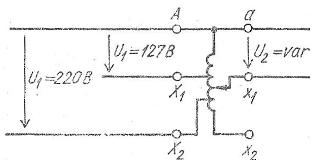
Schematic of a laboratory-controlled single-phase autotransformer
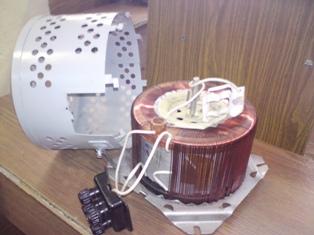
Laboratory autotransformer (LATR)
Three-phase autotransformers
Along with single-phase two-winding autotransformers, three-phase two-winding and three-phase three-winding autotransformers are often used.
In three-phase autotransformers, the phases are usually connected in a star with a pointed neutral point (Fig. 3). If it is necessary to reduce the voltage, electrical energy is supplied to terminals A, B, C and withdrawn from terminals a, b, s, and with an increase in voltage — vice versa. They are used as voltage reduction devices when starting powerful motors, as well as for stepwise regulation of terminal voltage. heating elements electric ovens.
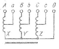
Rice. 3. Scheme of a three-phase autotransformer with a star connection of the winding phases with the neutral point removed
Three-phase high-voltage transformers with three windings are also used in high-voltage electrical networks.
Three-phase autotransformers, as a rule, on the side of higher voltage are connected in a star with a neutral wire. The star connection provides the voltage drop for which the autotransformer insulation is designed.
The use of autotransformers improves the efficiency of energy systems, reduces energy transmission costs, but leads to an increase in short-circuit currents.
Disadvantages of autotransformers
The disadvantage of the autotransformer is the need to insulate the two windings for higher voltage, since the windings are electrically connected.
A significant disadvantage of autotransformers is the galvanic connection between the primary and secondary circuits, which does not allow them to be used as feeders in 6-10 kV networks when the voltage drops to 0.38 kV, since 380 V is supplied to the equipment on which people work.
In the event of breakdowns due to the presence of an electrical connection between the windings in the autotransformer, the higher voltage can be applied to the lower winding. In this case, all parts of the operational installation will be connected to the high-voltage part, which is not allowed due to maintenance safety and the possibility of breaking the insulation of the conductive parts of the connected electrical equipment.
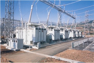 High voltage autotransformers