Short circuits, overloads, transient resistances. Fire safety measures
What is a short circuit and what causes a short circuit
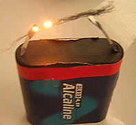
 Short circuits in wiring most often occur due to a violation of the insulation of conductive parts as a result of mechanical damage, aging, exposure to moisture and corrosive environments, as well as improper human actions. When there is a short circuit it increases amperage, and the amount of heat released is known to be proportional to the square of the current. So, if in a short circuit the current will increase 20 times, then the amount of heat released will increase about 400 times.
A thermal effect on the insulation of wires sharply reduces its mechanical and dielectric properties. For example, if the conductivity of electrical cardboard (as an insulating material) at 20 ° C is taken as a unit, then at temperatures of 30, 40 and 50 ° C it will increase by 4, 13 and 37 times, respectively. Thermal aging of the insulation most often occurs due to overloading of electrical networks with currents exceeding the long-term permissible for a given type and cross-section of wires.For example, for cables with paper insulation, their service life can be determined according to the well-known "rule of eight degrees": an increase in temperature for every 8 ° C reduces the service life of the insulation by 2 times. Polymeric insulating materials are also subject to thermal degradation.
The impact of moisture and a corrosive environment on the insulation of wires significantly worsens its condition due to the appearance of surface leakage. The resulting heat evaporates the liquid, leaving traces of salt on the insulation. When evaporation stops, the leakage current disappears. With repeated exposure to moisture, the process is repeated, but due to an increase in salt concentration, the conductivity increases so much that the leakage current does not stop even after the end of evaporation. In addition, small sparks appear. Subsequently, under the influence of the leakage current, the insulation carbonizes, loses its strength, which can lead to the appearance of a local arcing surface discharge that can ignite the insulation.
The danger of a short circuit in electric wires is characterized by the following possible manifestations of electric current: ignition of the insulation of wires and surrounding combustible objects and substances; the ability of the insulation of the wires to spread combustion when ignited by external sources of ignition; the formation of molten metal particles during a short circuit, igniting the surrounding combustible materials (the expansion speed of molten metal particles can reach 11 m / s, and their temperature is 2050-2700 ° C).
An emergency mode also occurs when electrical wires are overloaded.Due to incorrect selection, switching on or failure of consumers, the total current flowing through the wires exceeds the nominal value, that is, an increase in current density (overload) occurs. For example, when a current of 40 A flows through three series-connected pieces of wire of the same length but of different cross-section-10; 4 and 1 mm2, its density will be different: 4, 10 and 40 A / mm2. The last piece has the highest current density and, accordingly, the largest power losses. A wire with a cross section of 10 mm2 will slightly heat up, the temperature of a wire with a cross section of 4 mm2 will reach the permissible level, and the insulation of a wire with a cross section of 1 mm2 will just burn.
How short circuit current differs from overload current
 The main difference between short-circuit and overload lies in the fact that for short-circuit the violation of insulation is the cause of the emergency mode, and when overload — its consequence. Under certain circumstances, overloading of wires and cables due to the longer duration of the emergency mode is more dangerous for fire than a short circuit.
The base material of the wires has a significant influence on the ignition characteristics in case of overload. A comparison of the fire hazard indicators of wires of APV and PV brands, obtained during tests in the overload mode, shows that the probability of ignition of the insulation in wires with copper conducting wires is higher than that of aluminum wires.
Short-circuiting the same pattern is observed. The burning capacity of arc discharges in circuits with copper wires is higher than with aluminum wires.For example, a steel pipe with a wall thickness of 2.8 mm is burned (or combustible material on its surface is ignited) with a cross-section of an aluminum wire of 16 mm2 and with a copper wire with a cross-section of 6 mm2.
Current multiplicity is determined by the ratio of the short-circuit or overload current to the continuous allowable current for a given cross-section of the conductor.
Wires and cables with a polyethylene sheath, as well as polyethylene pipes when laying wires and cables in them, have the greatest risk of fire. Wiring in polyethylene pipes from the point of view of fire is a greater danger than wiring in vinyl plastic pipes, therefore the field of application of polyethylene pipes is much narrower. Overloading is especially dangerous in private residential buildings, where, as a rule, all consumers are fed from one network, and protective devices are often absent or designed only for short-circuit current. In high-rise residential buildings, there is also nothing to prevent residents from using more powerful lamps or turning on household electrical appliances with a total power greater than that for which the network is designed.
On cable devices (contacts, switches, sockets, etc.), the limit values of currents, voltages, power are indicated, and on terminals, connectors and other products, in addition, the largest cross-sections of the connected wires. To use these devices safely, you must be able to decipher these labels.
For example, the switch is marked «6.3 A; 250 V «, on the cartridge -» 4 A; 250 V; 300 W «, and on the extension -splitter -» 250 V; 6.3 A «,» 220 V. 1300 W «,» 127 V, 700 W «.«6.3 A» warns that the current passing through the switch should not exceed 6.3 A, otherwise the switch will overheat. For any lower current, the switch is suitable, because the lower the current, the less the contact heats up. The inscription «250 V» indicates that the switch can be used in networks with a voltage that does not exceed 250 V.
If you multiply 4 A by 250 V, you get 1000, not 300 watts. How do I associate a calculated value with a label? We must start from power. At a voltage of 220 V, the permissible current is 1.3 A (300: 220); at a voltage of 127 V — 2.3 A (300-127). A current of 4 A corresponds to a voltage of 75 V (300: 4). Inscription "250 V; 6.3 A «indicates that the device is designed for networks with a voltage of no more than 250 V and a current of no more than 6.3 A. Multiplying 6.3 A by 220 V, we get 1386 W (1300 W, rounded). Multiplying 6.3A by 127V, we get 799W (700W rounded). The question arises: is it not dangerous to round in this way? It is not dangerous because after rounding you get lower power values. If the power is less, then the contacts heat up less.
When an electric current flows through the contact connection due to the transient resistance of the contact connection, the voltage drops, power and energy are released, causing the contacts to heat up. An excessive increase in current in the circuit or an increase in resistance leads to an additional increase in the temperature of the contact and lead wires, which can cause a fire.
In electrical installations, permanent contact connections (soldering, welding) and detachable (with screw, plug, spring, etc.) and contacts of switching devices are used - magnetic starters, relays, switches and other devices specially designed for closing and opening of electric circuits, that is, for their commutation. In internal power networks from the entrance to the receiver of electricity electricity the load flows through a large number of contact connections.
Under no circumstances should the contact links be broken…. The studies carried out some time ago on the equipment of internal networks show that of all the examined contacts, only 50% meet the requirements of GOST. When the load current flows in a poor-quality contact connection, a significant amount of heat is released per unit time, proportional to the square of the current (current density) and the resistance of the actual contact points of the contact.
If the hot contacts come into contact with combustible materials, they may catch fire or char, and the insulation of the wires may catch fire.
The value of the contact resistance depends on the current density, the compression force of the contacts (the size of the resistance area), the material from which they are made, the degree of oxidation of the contact surfaces, etc.
To reduce the current density in the contact (and hence the temperature), it is necessary to increase the actual contact area of the contacts. If the contact planes are pressed against each other with some force, the small tubercles at the points of contact will be slightly crushed.Because of this, the sizes of the contact elemental areas will increase and additional contact areas will appear, and the current density, contact resistance and contact heating will decrease. Experimental studies have shown that there is an inverse relationship between contact resistance and the amount of torque (compression force). With a two-fold decrease in torque, the resistance of the contact connection of the APV wire with a cross section of 4 mm2 or two wires with a cross section of 2.5 mm2 increases by 4-5 times.
To remove heat from the contacts and dissipate it into the environment, contacts with a certain mass and cooling surfaces are made. Particular attention is paid to the places of connection of wires and their connection to the contacts of the input devices of the electrical receivers. On the movable ends of the wires, ears of various shapes and special clamps are used. The reliability of the contact is ensured by conventional washers, spring-loaded and with flanges. After 3–3.5 years, the contact resistance increases about 2 times. The resistance of the contacts also increases significantly during a short circuit as a result of a short periodic effect of the current on the contact. Tests show that contact joints with elastic spring washers have the greatest stability when exposed to adverse factors.
Unfortunately, "puck saving" is quite common. The washer should be made of non-ferrous metals such as brass. The steel washer is protected with an anti-corrosion coating.
