Three-phase alternating current
 Nowadays, it is the most common three-phase alternating current system around the world.
A three-phase electric circuit is called a system consisting of three circuits in which alternating currents operate, EMF of the same frequency, out of phase with each other by 1/3 of the period (φ=2π/ 3). Each individual circuit of such a system is briefly called its phase, and the system of three phase-shifted alternating currents in such circuits is simply called three-phase current.
Almost all generators installed in our power plants are three-phase current generators... In essence, each such generator is a connection in one electric machine of three alternators, designed in such a way that the induced in them EMF shifted relative to each other by one third of the period as shown in fig. 1.
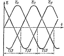
Rice. 1. Graphs of the time dependence of the EMF induced in the armature windings of a three-phase current generator
How such a generator is implemented is easy to understand from the circuit in fig. 2.
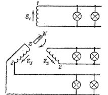
Rice. 2. Three pairs of independent wires connected to three armatures of a three-phase current generator feed the lighting network
There are three independent armatures located on the stator of an electric machine and offset by 1/3 of a circle (120O). An inductor common to all armatures rotates in the center of the electrical machine shown in the diagram in the form permanent magnet.
 In each coil an alternating EMF is induced same frequency, but the times when these emfs pass through zero (or through maximum) in each of the coils will be shifted by 1/3 of a period relative to each other because the inductor passes through each coil 1/3 of a period later from the previous one.
Each winding of a three-phase generator is an independent current generator and source of electrical energy. By connecting the wires to the ends of each as shown in fig. 2, we would get three independent circuits, each of which could power certain electrical receivers, for example electric lamps.
In this case, to transfer all the energy that is absorbed electrical receivers, six wires will be required. However, it is possible to connect the windings of a three-phase current generator in such a way that they handle four or even three wires, that is, significantly save wiring.
The first of these ways is called a star connection (Fig. 3).
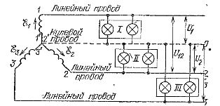
Rice. 3. Four-wire wiring system when connecting a three-phase generator with a star. Loads (groups of electric lamps I, II, III) are supplied with phase voltages.
We will call the terminals of the coils 1, 2, 3 the beginning, and the terminals 1′, 2′, 3′ the ends of the respective phases.
The connection of the stars is that we connect the ends of all the windings to one point of the generator, which is called the zero point or neutral, and we connect the generator to the receivers of electricity with four wires: three so-called linear wires coming from the beginning of windings 1, 2, 3 and neutral or neutral wire going from the zero point of the generator. This wiring system is called four-wire.
 The voltages between the zero point and the origin of each phase are called phase voltages, and the voltages between the origin of the windings, that is, points 1 and 2, 2 and 3, 3 and 1, are called line... Phase voltages usually mean U1, U2, U3, or in general form Uf and line voltage — U12, U23, U31, or in general form Ul.
Between amplitudes or mean values phase and line voltage when connecting the windings of the generator with a star, there is a ratio Ul = √3Uf ≈ 1.73Ue
So, for example, if the phase voltage of the generator is Uf = 220 V, then when connecting the windings of the generator in a star, the line voltage Ul — 380 V.
In the case of uniform loading of the three phases of the generator, that is, with approximately equal currents in each of them, the current in the neutral wire is zero... Therefore, in this case, you can remove the neutral wire and switch to an even more economical three-wire system. In this case, all loads are connected between the corresponding pairs of line conductors.
In an unbalanced load, the current in the neutral conductor is not zero, but generally speaking it is less than the current in the line conductors. Therefore, the neutral wire can be thinner than the line wire.
When operating three-phase alternating current, they strive to make the load on the different phases as equal as possible.That is why, for example, when arranging the lighting network of a large house with a four-wire system, a neutral wire and one of the linear ones are introduced into each apartment in such a way that on average each phase has approximately the same load.
Another way of connecting the generator windings, which also allows three-wire wiring, is the delta connection shown in fig. 4.
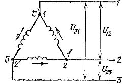
Rice. 4. Connection diagram of the windings of a three-phase generator with a triangle
Here, the end of each coil is connected to the beginning of the next one, so they form a closed triangle, and the line wires are connected to the vertices of this triangle - points 1, 2 and 3. When connected with a triangle, the line voltage of the generator is equal to its phase voltage: Ul = Ue.
Therefore, switching the windings of the generator from star to delta leads to a decrease in the network voltage in √3 ≈ 1.73 times... Delta connection is also permissible only with the same or almost the same phase load. Otherwise, the current in the closed loop of the windings will be too strong, which is dangerous for the generator.
When using three-phase current, separate receivers (loads) fed by separate pairs of wires can also be connected either in a star, that is, so that one end of them is connected to a common point, and the other three free ends are connected to the line wires of the network or with a triangle, that is, so that all loads are connected in series and form a common circuit, to points 1, 2, 3 of which the linear wires of the network are connected.
In fig. 5 shows the star connection of loads with a three-wire wiring system, and in fig.6 — with a four-wire wiring system (in this case, the common point of all loads is connected to the neutral wire).
In fig. 7 shows a delta load connection diagram for a three-wire wiring system.
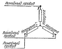
Rice. 5. Star connection of loads with three-wire wiring system
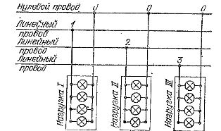
Rice. 6. Star connection of loads with four-wire wiring system
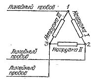
Rice. 7. Delta connection of loads with a three-wire wiring system
In practice, it is important to consider the following. When loads are delta connected, each load is under line voltage, and when star connected, under voltage √3 times less. For the case of a four-wire system, this is clear from fig. 6. But the same is the case with a three-wire system (Fig. 5).
Between each pair of line voltages here, two loads are connected in series, the currents in which are phase-shifted by 2π/ 3. The voltage in each load is equal to the corresponding network voltage divided by √3.
Thus, when switching loads from star to delta, the voltages at each load, and therefore the current in it, increase by √3 ≈ 1.73 times. If, for example, the line voltage of a three-wire network is 380 V, then when it is connected in a star (fig. 5) the voltage of each of the loads will be equal to 220 V, and when connected with a triangle (fig. 7) it will be equal to 380 V.
Information from a physics textbook edited by G.S. Landsberg was used in the preparation of the article.