AC power supply and power losses
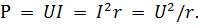
 The power of a circuit that has only active resistances is called the active power P. It is calculated as usual using one of the following formulas:
Active power characterizes the irreversible (irreversible) consumption of current energy.
In chains alternating current there are many more causes causing unrecoverable energy losses than in DC circuits. These reasons are as follows:
1. Heating the wire by current… For direct current, heating is almost the only form of energy loss. And for alternating current, which is the same in value with direct current, the energy loss for heating the wire is greater due to the increase in resistance of the wire due to the surface effect. The higher current frequency, the more it affects surface effect and the greater loss for heating the wire.
2. Losses to create eddy currents, otherwise called Foucault currents… These currents are induced in all metallic bodies in a magnetic field generated by alternating current. From action eddy currents metal bodies heat up.Particularly significant eddy current losses can be observed in steel cores. Energy losses to create eddy currents increase with increasing frequency.
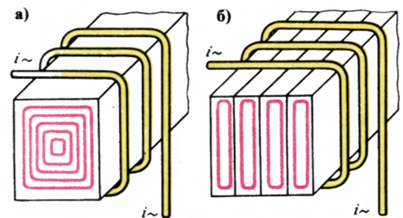
Eddy currents — in a massive core, b — in a lamellar core
3. Loss of magnetic hysteresis... Under the influence of an alternating magnetic field, the ferromagnetic cores are remagnetized. In this case, mutual friction of the core particles occurs, as a result of which the core heats up. As the frequency increases the losses from magnetic hysteresis is growing.
4. Losses in solid or liquid dielectrics... In such dielectrics, the alternating electric field causes polarization of molecules, that is, charges appear on opposite sides of the molecules, equal in value but different in sign. Polarized molecules rotate under the action of the field and experience mutual friction. Due to it, the dielectric heats up. As the frequency increases, its losses increase.
5. Insulation Leakage Losses… The insulating substances used are not ideal dielectrics and leakage leaks are observed in them. In other words, the insulation resistance, although very high, is not equal to infinity. This type of loss also exists in direct current. At high voltages, it is even possible for charges to flow into the air surrounding the wire.
6. Losses due to radiation of electromagnetic waves… Any AC cable emits electromagnetic waves, and as the frequency increases, the energy of the emitted waves increases sharply (proportional to the square of the frequency).Electromagnetic waves irreversibly leave the conductor, and therefore the energy consumption for the emission of waves is equivalent to losses in some active resistance. In radio transmitter antennas, this type of loss is useful energy loss.
7. Losses for power transmission to other circuits... As a consequence phenomena of electromagnetic induction some AC power is transferred from one circuit to another located nearby. In some cases, such as in transformers, this energy transfer is beneficial.
The active resistance of the AC circuit takes into account all the listed types of non-recoverable energy losses... For a series circuit, you can define the active resistance as the ratio of active power, the strength of all losses to the square of the current:

Thus, for a given current, the active resistance of the circuit is the greater, the greater the active power, i.e., the greater the total energy losses.
The power in the circuit section with inductive resistance is called reactive power Q... It characterizes the reactive energy, that is, the energy that is not irretrievably consumed, but only temporarily stored in a magnetic field. To distinguish it from active power, reactive power is measured not in watts, but in reactive volt-amperes (var or var)... In this respect, it was previously called anhydrous.
Reactive power is determined by one of the formulas:
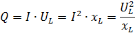
where UL is the voltage in the section with inductive resistance xL; I is the current in this section.
For a series circuit with active and inductive resistance, the concept of total power S is introduced... It is determined by the product of the total circuit voltage U and the current I and is expressed in volt-amperes (VA or VA)

The power in the section with active resistance is calculated by one of the above formulas or by the formula:

where φ is the phase angle between voltage U and current I.
The coefficient of cosφ is the power factor… It is often called «cosine phi»… The power factor shows how much of the total power is active power:

The value of cosφ can vary from zero to unity, depending on the ratio between active and reactive resistance. If there is only one in the circuit reactivity, then φ = 90 °, cosφ = 0, P = 0 and the power in the circuit is purely reactive. If there is only active resistance, then φ = 0, cosφ = 1 and P = S, that is, all the power in the circuit is purely active.
The lower the cosφ, the smaller the active power share of the apparent power and the higher the reactive power. But the work of current, that is, the transition of its energy into some other type of energy, is characterized only by active power. And reactive power characterizes the energy that fluctuates between the generator and the reactive part of the circuit.
For the electrical grid, it is useless and even harmful. It should be noted that in radio engineering reactive power is necessary and useful in a number of cases. For example, in oscillating circuits, which are widely used in radio engineering and are used to generate electrical oscillations, the strength of these oscillations is almost purely reactive.
The vector diagram shows how changing cosφ changes the receiver current I with its power unchanged.
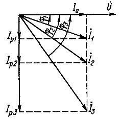
Vector diagram of receiver currents at constant power and various power factors
As can be seen, the power factor cosφ is an important indicator of the degree of utilization of the total power developed by the alternating EMF generator... It is necessary to pay special attention to the fact that at cosφ <1 the generator must create a voltage and current whose product is greater than active power. For example, if the active power in the electrical network is 1000 kW and cosφ = 0.8, then the apparent power will be equal to:
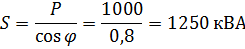
Suppose that in this case the real power is obtained at a voltage of 100 kV and a current of 10 A. However, the generator must generate a voltage of 125 kV in order for the apparent power to be

It is clear that the use of a generator for a higher voltage is disadvantageous and, moreover, at higher voltages it will be necessary to improve the insulation of the wires to avoid increased leakage or occurrence of damage. This will lead to an increase in the price of the electricity grid.
The need to increase the generator voltage due to the presence of reactive power is characteristic of a series circuit with active and reactive resistance. If there is a parallel circuit with active and reactive branches, then the generator must create more current than is needed with a single active resistance. In other words, the generator is loaded with additional reactive current.
For example, for the above values P = 1000 kW, cosφ = 0.8 and S = 1250 kVA, when connected in parallel, the generator should give a current of not 10 A, but 12.5 A at a voltage of 100 kV.in this case, not only the generator must be designed for a larger current, but the wires of the electric line through which this current will be transmitted will have to be taken with a greater thickness, which will also increase the cost per line. If in the line and at the windings of the generator there are wires designed for a current of 10 A, then it is clear that a current of 12.5 A will cause increased heating in these wires.
Thus, although the extra reactive current transfers the reactive energy from the generator to reactive loads and vice versa, but creates unnecessary energy losses due to the active resistance of the wires.
In existing electrical networks, sections with reactive resistance can be connected both in series and in parallel with sections with active resistance. Therefore, generators must develop increased voltage and increased current to create, in addition to useful active power, reactive power.
From what has been said, it is clear how important it is for electrification increasing the cosφ value… Its reduction is caused by the inclusion of reactive loads in the electrical network. For example, electric motors or transformers that are idling or not fully loaded create significant reactive loads because they have relatively high winding inductance. To increase cosφ, it is important that motors and transformers operate at full load. It exists several ways to increase cosφ.
In conclusion, we note that all three forces are interconnected by the following relation:
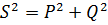
that is, apparent power is not the arithmetic sum of active and reactive power.It is customary to say that the power S is the geometric sum of the powers P and Q.
See also: Reactance in electrical engineering