Pipe Stoppers — Device, Features, Application, Advantages and Disadvantages
 The use of lightning rods does not completely exclude lightning damage to electrical installations, especially power lines, since the probability of lightning strike for overhead power lines can be relatively high and, moreover, they are often carried out without any protection of the conductors at all. Overvoltages that occur on the lines during lightning strikes reach substations (which is why they are called surges) and can pose a danger to the insulation of the equipment installed there.
To prevent damage to any insulating structure, include a spark, volt-second (whose characteristic must lie below the volt-second characteristic of the protected insulation.If this condition is met, the drop of the overvoltage wave will in all cases cause the breakdown of the spark gap, followed by a sharp drop ("disruption") of the voltage across the spark gap and the protected insulation. an impulse current through the spark gap will start to flow due to the voltage of the industrial frequency of the electrical installation — the accompanying current.
In installations with an earthed neutral or in the event of a two- or three-phase spark gap failure, the subsequent arc may not extinguish itself, and the impulse fault in this case will become a stable short circuit, leading to an interruption of the installation . Therefore, in order to avoid such a shutdown of the installation, it is necessary to extinguish the next arc through the spark gap.
Devices that provide not only isolation protection against overvoltage, but also extinguish the next arc in a time less than the duration of the relay protection, are called protective arresters in contrast to conventional candles, which are usually called protective gaps (PZ).
Pipe stops together with valve are the main types of retainers. They differ in the principle of subsequent arc extinguishing. In tube arresters, the arc is extinguished by creating an intense longitudinal burst, and in valve arresters, the arc is extinguished due to a reduction in the subsequent current by means of an additional resistance connected in series with the spark gap.
A tube spark gap (Fig. 1, a) is a tube 2 made of insulating gas-generating material, inside which there is an unregulated arc extinguishing gap S1 formed by a rod electrode 3 and a flange 4.The spark is separated from the operating voltage by an external spark gap, since the tube 2 is not intended for long-term presence under voltage due to the decomposition of the gas-generating material under the influence of leakage leaks. The second flange 1 of the limiter is grounded.
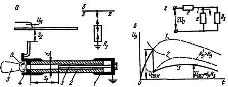
Rice. 1. Tube arrester: a — device and switching circuit, b — conventional notation of the diagrams, c — voltage in the arrester, d — equivalent circuit.
With an overvoltage in the network (Fig. 1, c), both spark gaps break and the overvoltage wave (curve 1) is interrupted. An accompanying current begins to flow along the path created by the pulse discharge, and the spark discharge turns into an arc discharge. Under the action of the high temperature of the arc channel of the accompanying current, the material of the tube decomposes with the release of a large amount of gases, the pressure in it sharply increases (up to tens of atmospheres) and the gases are forced out through the flange opening 4, creating an intense longitudinal blast. As a result, the arc is extinguished when the current first passes through zero.
When the spark gap is triggered, it emits incandescent ionized gases in the form of a torch 5 1.5 - 3.5 m long and 1 - 2.5 m wide (depending on the nominal voltage of the spark gap) and a sound is heard , resembling a shot I heard. Therefore, in order to prevent phase-to-phase failures, when installing arresters, it is necessary to ensure that the current-carrying parts of adjacent phases do not fall into the discharge zone.The tripping voltage of the arresters can be adjusted by changing the distance of the external spark gap, but they cannot be reduced below a certain minimum, because this causes the arresters to trip too often and increase their wear.
Since the electric field of the rod-shaped electrodes of the tube spark gap is highly inhomogeneous, its volt-second characteristic has a decreasing character in the region up to 6-8 μs, which is not consistent with the flat volt-second characteristics of transformers and electrical machines. A certain intensity of gas formation is required for successful arc quenching, therefore there is a lower limit of currents to be cut at which the discharger can still quench the arc within 1-2 half cycles.
The upper limit of interrupting currents is also limited, since too intense gas formation can lead to the destruction of the arrester (rupture of the tube or destruction of the flanges).
The range of interrupting currents is indicated in the type designation of the arrester, for example, RTV 35 / (0.5 — 2.5) means a tube arrester 0.5 — 2.5 vinyl plastic for 35 kV with an interruption current range of 0.5 — 2.5 kA.
As the length of the arc suppression gap decreases and its diameter increases, both limits of the discharge currents are shifted to larger values.
Since the operation of the arrester is accompanied by the burning of part of the material of the arc suppression tube, after 8 — 10 operations, when the diameter increases by 20 — 25% compared to the initial one, the arrester becomes unusable (since the limits of the currents, interrupted by it, are changed) and must be replaced.
In order to take into account the number of operations, the pipe limiters are equipped with an activation indicator in the form of a metal strip 6 (see Fig. 1, a), not unfolded by the gases emitted by the limiter. Currently, the industry produces RTF type pipe restraints in which the gas is generated from the fiber pipe, and RTV type with vinyl plastic pipe.
Due to the low mechanical strength of the fiber, it is enclosed in a thick tube of Bakelized paper, which, in order to reduce its hygroscopicity, is covered with a moisture-resistant varnish (usually perchlorovinyl enamel), which can withstand atmospheric influences in summer and winter periods well . A characteristic feature of the RTF arresters is the presence of a chamber at the closed end of the tube, which enhances the longitudinal blowout when the current passes through the zero value and thus contributes to arc extinguishing.
In RTV restrictors, the gas is generated by a vinyl plastic tube, which has a higher gas generation capability and insulating properties that are well preserved even when working outdoors in all weathers. RTV arresters have a simpler design (no internal chamber, no painting required) and higher upper limits of interrupting currents (15 kA instead of 7-10 kA for RTF arresters).

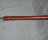
Rice. 2. Pipe stop RTV-20-2 / 10
For operation in networks with very large intermittent currents (up to 30 kA), reinforced limiters of the RTVU type are produced, the increased mechanical strength of which is achieved by winding a vinyl plastic tube with layers of glass tape impregnated with a weather-resistant epoxy compound.
The impulse carrying capacity of tube arresters, which pass practically the entire lightning current through them when it strikes the line, is quite high and amounts to 30–70 kA.
The selection of pipe arresters is made according to the nominal voltage of the network and the limits of the short-circuit currents of the network at the point of their installation. The maximum short-circuit current is calculated when all network elements (lines, transformers, generators) are turned on, taking into account the aperiodic component of the short-circuit current, the minimum current — with a network circuit with partially disconnected elements (for example, for overhaul) and without the aperiodic component is considered. The short circuit current limits found. must fit within the interrupting current limits of the pipe arrester.
Tube arresters are produced for voltages from 3 to 220 kV, interrupting currents range from 0.2 — 7 and 1.5 — 30 kA at voltage 3 — 35 kV to 0.4 — 7 and 2.2 — 30 kA at voltage 110 kV. The 220 kV arrester consists of two 110 kV tube arresters connected by a steel cage with discharge pipes.
The main disadvantages of tube arresters are the presence of a discharge zone, a steep break in the surge wave, a short circuit (albeit short-term) from the lines to ground, and a particularly steep volt-second characteristic, which precludes the possibility of wide use of tube arresters as a protection device of substation equipment. The disadvantage of pipe limiters is the presence of limiting interrupted currents, which complicates their production and operation.
Due to their simplicity and low cost, pipe arresters are widely used as auxiliary means of substation protection, for the protection of low-power and low-criticality substations, as well as individual sections of lines.
Currently, tube and valve limiters are gradually being replaced by non-linear voltage limiters (limiters)... They are serially connected metal oxide varistors (non-linear resistors) without sparks, enclosed in a porcelain or polymer case.